© 2021 Thorlabs
2 Getting Started
5
2 Getting Started
Prior to operate a LDC200C Series controller, check if the set line voltage matches with your
local power supply and if the appropriate fuses are inserted.
The laser diode controller LDC2xxC operates at fixed line voltages of
100 V +15% / -10% ( 90 V … 115 V)
115 V +15% / -10% (104 V … 132 V)
230 V +15% / -10% (207 V … 264 V)
line frequency 50 … 60 Hz.
The line voltage setting can be changed from the rear without opening the unit.
1. Turn off the controller and disconnect the mains cable.
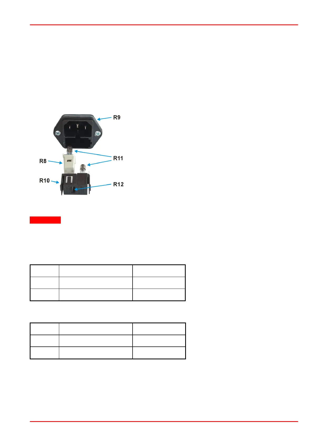
2. The fuse holder (R10) is located below the 3-pole power
connector of the mains jack (R9). Release the fuse holder
by pressing its plastic retainers with the aid of a small
screwdriver. The retainers are located on the right and left
side of the holder and must be pressed towards the center.
3. Unplug the white line voltage switch/indicator (R8, con-
taining the left fuse) from the fuse holder (R10), rotate it
until the appropriate voltage marking (100V, 115V, or
230V) is on target for the cutout (R12) of the fuse holder,
and plug it back into the fuse holder. Press in the fuse
holder until locked on both sides. The appropriate line
voltage marking must be visible in the cutout (R12) of the fuse holder.
Attention
If you have changed to or from 230 V, also change the mains fuses to the correct value given
below:
Fuse types
LDC200VC, LDC201CU, LDC202C, LDC205C, LDC210C, and LDC220C:
LDC240C:
All fuses must meet IEC specification 60127-2/III, time characteristic: time-lag (T), 250V AC,
size 5 x 20 mm.
Connect the unit to the power line using the supplied cable. Turn the unit on by pressing the
line switch.
If required, the chassis ground can be connected to ground potential via the connector jack
(R5). The ground pin of the laser diode is internally connected to chassis ground.

 Loading...


