Page 12 10997-D02
MAX300 Series 3-Axis Flexure Stages
Chapter 4 Installation
4.1 Unpacking
4.2 Attaching to a Work Surface
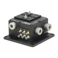
The base of the NanoMax is provided with a number of fixing holes and slots for
attachment to metric or inch optical tables, as supplied by Thorlabs and other
manufacturers.
When mounting the NanoMax close to other equipment, ensure that the travel of the
moving platform is not obstructed. If the moving platform is driven against a solid
object, damage to the internal flexures could occur. The range of travel on each axis
is 4 mm total, that is ± 2 mm about the nominal position.
Note
Retain the packing in which the unit was shipped, for use in future transportation.
Caution
Once removed from its packaging, the NanoMax is easily damaged by
mishandling. The unit should only be handled by its base, not by the top
platform or any attachments to the top platform.
 Loading...