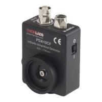
InGaAs Amplified Detector Chapter 4: Operation
Page 6 13122-D02
4.5. Terminating Resistance
A load resistance is used to convert the generated photocurrent into a voltage
(V
OUT
) for viewing on an oscilloscope:
Depending on the type of the photodiode, load resistance can affect the
response speed. For maximum bandwidth, we recommend using a 50 coaxial
cable with a 50 terminating resistor at the opposite end of the cable. This will
minimize ringing by matching the cable with its characteristic impedance. If
bandwidth is not important, you may increase the amount of voltage for a given
light level by increasing R
LOAD
. In an unmatched termination the length of the
coaxial cable can have a profound impact on the response, so it is recommended
to keep the cable as short as possible.
The maximum output of the PDA10CF(-EC) is 10 volts for high impedance loads
(i.e. R
Load
> 5 k) and 5 V for 50 loads. Adjust the gain so that the measured
signal level out of the PDA10CF(-EC) is below 10 volts (5 volts with a 50 load)
to avoid saturation.
For low terminating resistors, <5 k or 1% error, an additional factor needs to be
considered. As described above the output includes a 50 series resistor (R
S
).
The output load creates a voltage divider with the 50 series resistor as follows:
∗∗∗