Compact Stabilized Light Sources Chapter 4: Operation
Rev F, October 14, 2021 Page 11
As shown in Figure 10, the fiber coupler is installed onto the light source main body
with a quick release blade mechanism and secured by a set screw. For free space
applications, loosen the set screw with the included 0.050" (1.3 mm) hex key and
turn the fiber coupler counterclockwise to unlock and remove the fiber coupler
After remove the fiber coupler, users can see the collimating lens in the light source
and get access to a roughly collimated beam.
The SLS201L light source is shipped with a 1 m long, SMA to SMA fiber patch
cable with below specs:
Diameter
Diameter
Range
The SLS202L light source does not include any fiber patch cable, it is
recommended to use with fluoride fibers which are also available on Thorlabs
website: www.thorlabs.com
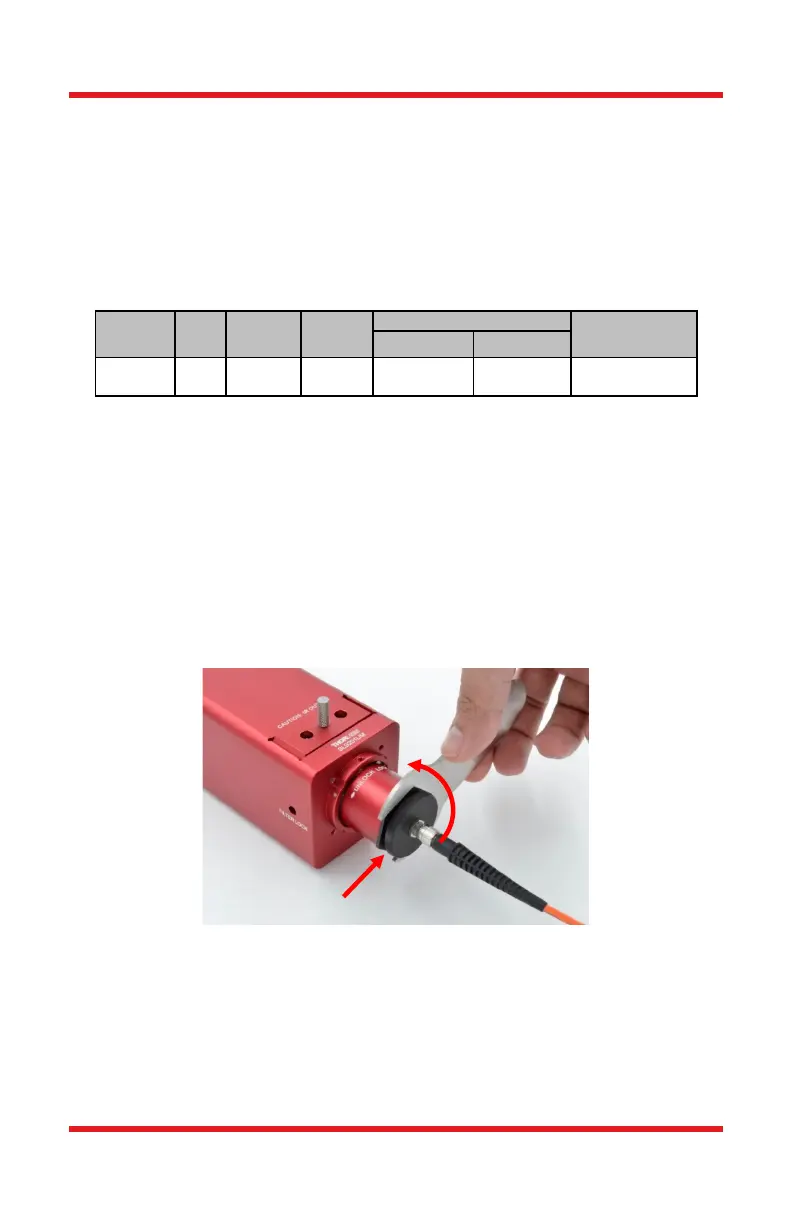
4.6. Adjusting Fiber Coupler Position
The fiber adapter is pre-adjusted to its optimum position before shipping out. But
if really necessary, it is also allow users to do adjustment. As shown in below
Figure 11, use the included 30 mm hex wrench to loosen the external retaining
ring by turning it counterclockwise. Then rotate the SMA fiber adapter to adjust its
position.
Figure 11 Adjust Fiber Adapter Position
4.7. Collimating Accessory (Optional)
Thorlabs also offer collimators for SLS201L and SLSL202L separately as optional
accessories for the light source. They are available on Thorlabs website:
www.thorlabs.com
for Position Adjustment
 Loading...