11
Mechanical Limit Switches.
Before attempting to move the crosshead in either direction it will be required to set the mechanical
crosshead limit switches. The purpose of the limit switches is to reduce the travel of the crosshead
enabling a safe working area. A typical example is to protect the load cell and attachments for
unforeseen over travel and in doing so avoid a collision. These limit switches are located on the left
hand side of the machine.
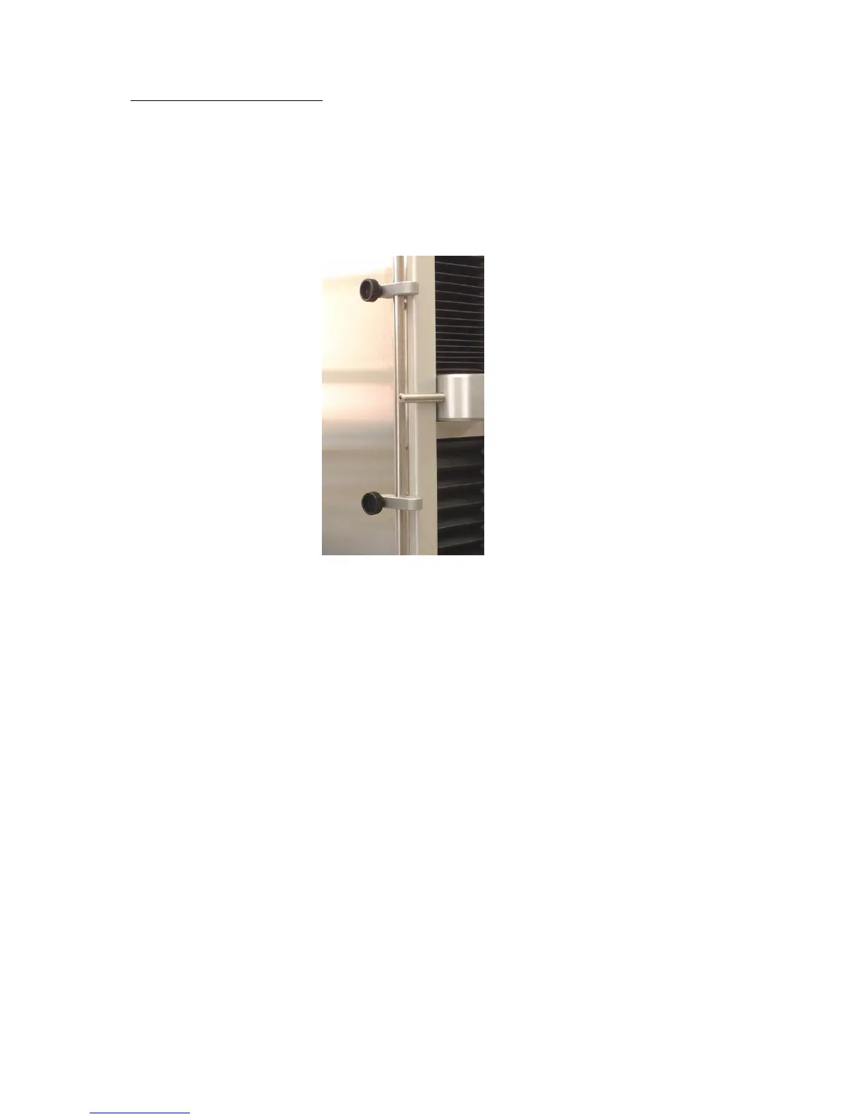
The figure below shows the location of the mechanical crosshead limit switches:
The limit switches are held in position by a locking screw. To set the limit switch, unlock it by turning
the locking screw in the counterclockwise direction and slide to the required new position. To lock the
limit switch, rotate the locking screw in the clockwise direction. (Note: To eliminate slippage, re-tighten
locking screw securely).
The diagrams below indicate mechanical crosshead limit switches:
Release Upper Limit Switch, move Release Lower Limit Switch, move
crosshead to a new position, slide crosshead to a new position, slide
limit switch to crosshead striker, limit switch to crosshead striker,
Re-tighten. Re-tighten.
 Loading...