98
98
NA11 - Manual - 02 - 2009
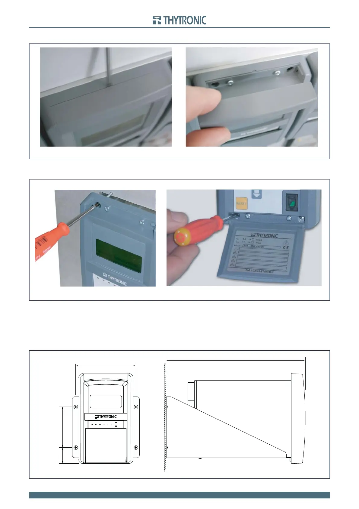
INSTALLATION
Remove the upper tile and open the little door to access the fastening screws.
The fi xed case is fastened by means of four screws onto the panel as indicated in the drawing.
Projecting mounting
Remove the ground screw and open the little door to access the fastening screws.
Make all connections and join the relay to the framework with front and earth screws.
In case of side-by-side mounting of several relays, the minimum fi xing distance is determined by the
dimensions of the mounting plate indicated in the overall dimensions drawing, increased horizontally
and vertically by as much as needed to allow room for the wiring and to ensure an adequate toler-
ance between devices.
•
•
•
•
Remove-tile.ai
Removing tie to access the fastening screws
Remove-tile.ai
Removing tie to access the fastening screws
Flush-mount1.ai
Four screws
Flush-mount1.ai
Four screws
Projecting mounting
Projecting.ai
ON 321 54
TRIP
START
120
8031
275
Projecting mounting
Projecting.ai
ON 321 54
TRIP
START
120
8031
275