11-4
ZR Owner’s Manual
OM_ZR_0913RevA
CHAPTER 11: CASTERS And FORKS
Note: TiLite designs its rigid wheelchairs to be exible for improved maneuverability and increased ride comfort.
However, this exibility requires that your chair be set up properly. The following procedure will enable you to set up
your TiLite rigid wheelchair so it will perform to its potential.
1. Place the wheelchair on a smooth, level surface with the casters trailing rearward.
2. Before making any adjustments to the chair, it is important to check the following:
a. The tires are properly inated to the PSI rating shown on the sidewall of the tire.
b. The camber tube is properly centered on the frame side to side and the camber tube is straight relative to the
rear of the frame. For adjustments see “Replacing the Camber Tube” on page 8-2.
c. The toe-in/toe-out is correctly set up (see “Adjusting Toe-In/Toe-Out” on pages 8-2 and 8-3).
All items in this list are performed at the factory to ensure proper frame alignment before shipping. If an
adjustment still needs to be made, complete it before proceeding. If no adjustment is needed, proceed to Step 3.
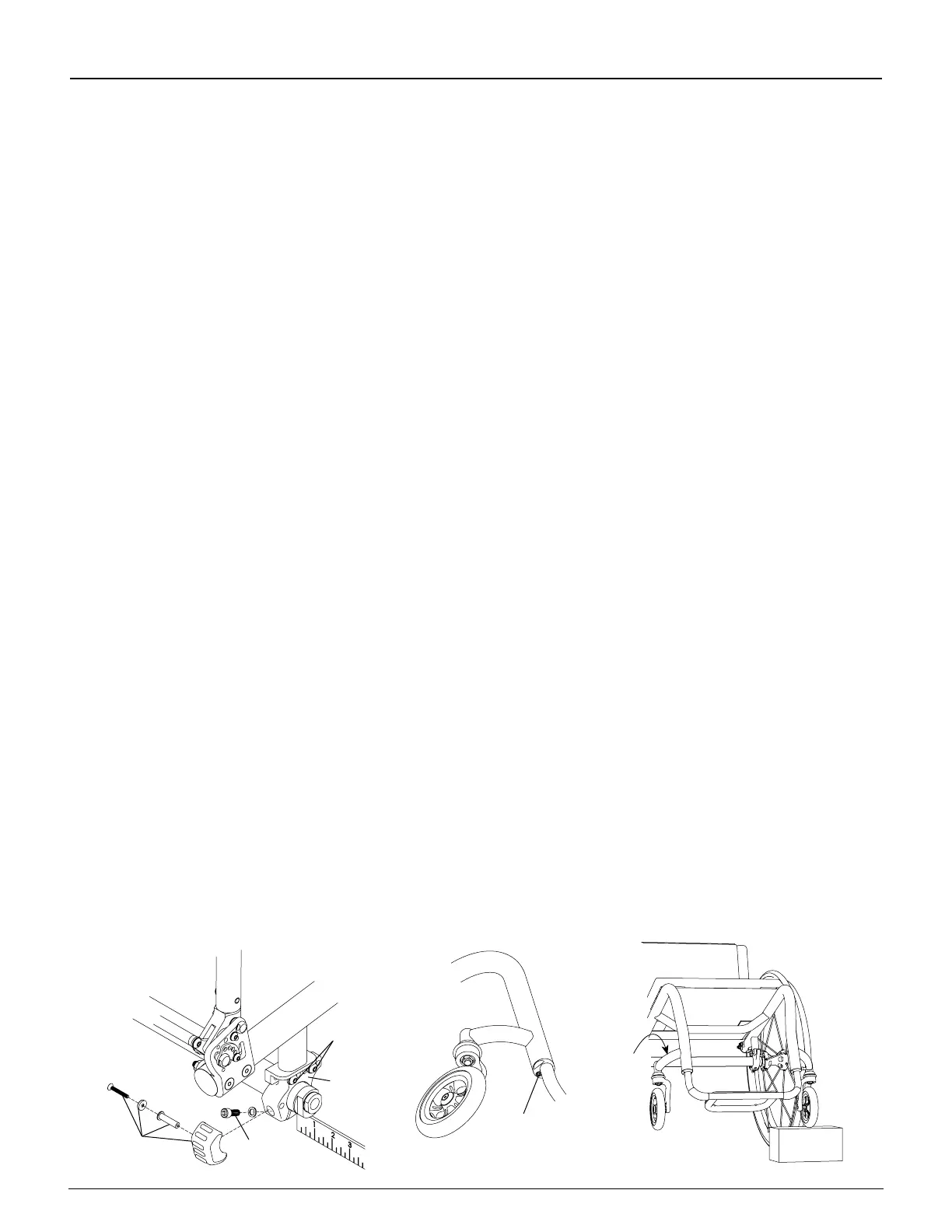
3. Loosen, but do not remove, the Allen screw in the footrest clamp only on the side of the oating caster as shown
in Figure 11-5. Once the screw is loose and the full head of the screw is exposed, strike the Allen wrench with a
mallet upward to release the internal wedge in the footrest clamp. See “Titanium Footrest with Flat ABS Cover -
Adjusting the Height” on page 3-2.
4. If your chair has a bumper assembly, this assembly will need to be removed. Loosen, but do not remove, all of
the Allen screws in the camber tube clamp on the side opposite the oating caster as shown in Figure 11-4. Do
not loosen the two CG bracket Allen screws too much as it will allow the clamp to slide within the CG bracket.
5. Wiggle the chair and let it settle on to the at surface to release any bind that may have existed within the chair
assembly.
6. Make sure your footrest is set to your desired seat-to-footrest measurement, and, using a ruler or measuring tape,
make sure the left and right sides of the footrest are the same distance from the level surface. It is important
to have both sides of the footrest level and the footrest clamp screw tightened before the camber tube mount
assemblies are tightened.
7. Tighten the footrest clamp screw.
8. Tighten the camber clamp screws starting with the uppermost screws and working downward.
9. If the above adjustments correct the oater and all four wheels are at on the level surface, you are nished with
your adjustment. If a caster is still oating, repeat Steps 3 through 8. If you continue to have a oater, proceed to
Steps 10 through 13.
10. Loosen, but do not remove, the Allen screw in the footrest clamp only on the side of the oating caster as shown
in Figure 11-5. Once the screw is loose and the full head of the screw is exposed, strike the Allen wrench with a
mallet upward to release the internal wedge in the footrest clamp. See “Titanium Footrest with Flat ABS Cover -
Adjusting the Height” on page 3-2.
11. Place a wood block under the other caster (which is not oating) as shown in Figure 11-6.
12. Apply gentle downward pressure on the caster mount of the oating caster. It is advisable that you have
an assistant to place downward pressure on the opposite side of the chair at the backrest when making this
adjustment.
13. Remove the wood block and check to see if the caster still oats. If the caster no longer oats, securely tighten
the Allen screw on the footrest clamp. If the caster still oats, or if the other caster starts to oat, check that the
footrest is level and repeat Steps 10 through 13 until the caster no longer oats.
14. If the oater continues and cannot be corrected using these steps, please contact TiLite Customer Service.
Figure 11-4
Allen Screws on the Camber Clamp
Camber
Clamp
Allen
Screw
Bumper
Assembly
Figure 11-5
Allen Screw on Footrest Clamp
Figure 11-6
Fixing a Floating Caster
Apply
Pressure
Here
Allen
Screw
Allen
Screw