11
5.3 Purpose, Dismounting, and Replacement of the Flame Detector
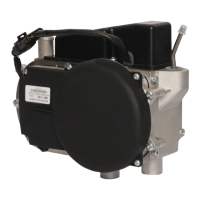
The ame detector (Fig. 5) is used
to detect ame in the combustion
chamber. It is comprised of a pipe
with a thermocouple with two
outputs inside.
Check the ame detector if malfunc-
tions described in Table 2 occur.
If the fault appears during the pre-
heater startup:
Disconnect the control unit connec-
tors from the harness
Remove the screws fastening the
control unit to the air blower housing
Disconnect the LED wires from the
control unit
Check the ame detector for open
circuit with a multimeter. An open
circuit means the ame detector
is faulty
Check the insulation resistance
between the outputs and the FD
housing. It must not be lower than
100 MΩ at 100 V. Measure the resis-
tance at 15–35ºС and relative humid-
ity not above 80%. If the insulation
resistance does not meet this
criterion, replace the FD.
If an error appears during the heating
element operation, there is either a
crack in the weld of the FD thermo-
couple (i.e. the circuit is open), or
the polarity of the FD connection is
reversed. The fault may be revealed
using two methods:
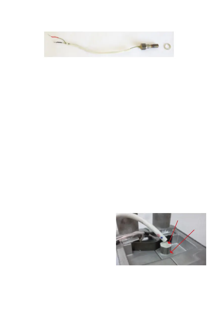
Method 1.
Remove the FD from the housing
(Fig. 6), connect the terminals of the
FD to a multimeter (at the tempera-
ture measuring terminals), and heat
up the FD, for instance, with a lighter.
The temperature must increase
gradually. If it increases in surges or
goes down to the initial value, the FD
is damaged. In this case, however,
the circuit may close after the FD
has cooled down.
Fig. 5. Flame detector
Fig. 6. Flame detector
Flame Detector
Washer