23
11. Pinout and Replacement of the Control Box
Pin Number Purpose
1 Ground Black 16 AWG
2 + 12 Volt Red 16 AWG
3 Fans (-) Black 18 AWG
4 Fans (+) Red 18 AWG
Fuses Purpose
1. Green Control Box 30 amp
2. Tan Touch Panel 5 amp
3. White Fans 25 amp
Pin Number Purpose
1 Not Used
2 Heater wire (GND) Blue
3 Touch Screen (GND) Blue
4 Heat Exchanger
Black/
White
5 Tank Sensor
Black/
White
6 Air Sensor Blue
7 Heater Data Green
8 Tank Relay 12 V Black
9 Solenoid Valve Black
10 Touch Screen Data Green
11 Heater Data 2 White
12 Touch Screen Data 2 White
13 Heat Exchanger White
14 Tank Sensor White
15 Air Sensor White
16 Touch Screen Red
17 Tank Relay 12 V Red
18 Solenoid Valve Red
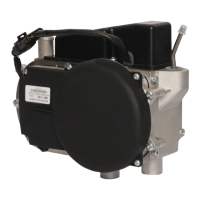
All of the data and power in the
system is ran through the control
box, except for the power to the
Binar, circulation pump, and fuel
pump. If you are having electrical
troubles with the system check
the fuses in the control box rst.
Check the pins placements and
wiring for the control box. If you
are still having trouble you will
need to replace the control box.
To replace the control box simply
unplug the control box and re-
place it with the new unit.
Fig. 18. Timberline Control Board
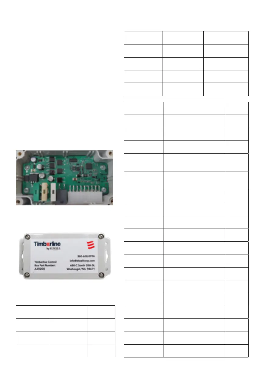
Fig. 18.a. Timberline Control Box