4
Load
Switch Live (Brown or Red) to SL
Neutral (Blue or Black) to N OUT
230V 50Hz Mains Supply
Live (Brown or Red) to L
Neutral (Blue or Black) to N
Note: this device needs to be left to charge for
a minimum of 15 minutes once powered up,
before it will operate.
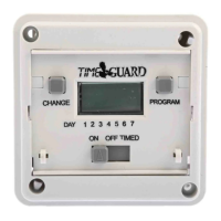
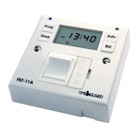
5. Connection Diagram
• The terminals are marked as follows
on the rear of the wall plate;
NTT03 – 230V Mains Voltage Switching
SL N
OUT
N L
230V 50Hz
Mains SupplyLoad