4 5
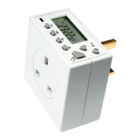
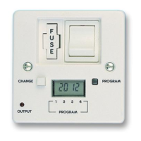
Illuminated
screen
• Remove the product and drill out the lower
mounting hole again taking care to avoid
any joists, electrical cables or water/gas pipes
that may be hidden beneath the surface.
Insert the rawl plug into the hole.
• The 230V 50Hz supply and load cables can
enter through the rear knock outs or the front
cable entry ports provided. If the rear knock
outs are being used, remove the blanking
plates and pass the supply and load cables
through the holes.
• Place the key hole in the top of the product
again, over the screw head, and slide down.
• Secure the unit to the wall using the lower
mounting screw.
• If the wiring is through the front cable entry
ports, use the cable clamps provided to
secure the supply and load cables.
• Terminate the supply and load cables to
the terminal block ensuring correct polarity
is observed and that all bare conductors
are sleeved. Please note the connections are
marked beneath the terminal block
(see section 5. Connection Diagram).
• Secure the terminal cover back into place
using the fixing screw.