5 6
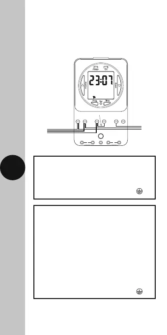
5. Connection Diagram
• The terminals are marked as follows
on the bottom of the wall plate;
230V Mains Voltage Switching
230V 50Hz Mains Supply
Live (Brown or Red) to L
Neutral (Blue or Black) to N
Earth (Green/Yellow) to
Load
Switch Live (Brown or Red) to either;
Normally OPEN to mains voltage
appliance e.g. Immersion Heater 2
Normally CLOSED to mains voltage
appliance e.g. Fan 3
Leave the ‘Link’ or ‘Bridge’
wire between L & 1
Neutral (Blue or Black) to N
Earth (Green/Yellow) to
EN L1 23
Link or ‘bridge wire’
230V 50Hz
Mains Supply
230V 50Hz
Mains Supply
EN L1 23
Load
Load
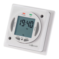
Note: this device needs to be left to charge for
a minimum of 15 minutes once powered up,
before it will operate.