FINCH II Installation & Operation Manual
TPM 010, Rev 7.0
www.titanlogix.com Pg. 10
First TD100 Power (black wire) to FINCH TD100 #1: PWR (BLACK) (3)
First TD100 Ground (white wire) to FINCH TD100 #1: GND (WHITE) (2)
First TD100 SV Bus (red wire) to FINCH TD100 #1: SV (RED) (1)
Complete these Steps for the optional second TD100 transmitter.
I. Second TD100 Power (black wire) to FINCH TD100 #2: PWR (BLACK) (3)
II. Second TD100 Ground (white wire) to FINCH TD100 #2: GND (WHITE) (2)
III. Second TD100 SV Bus (red wire) to FINCH TD100 #2: SV (RED) (1)
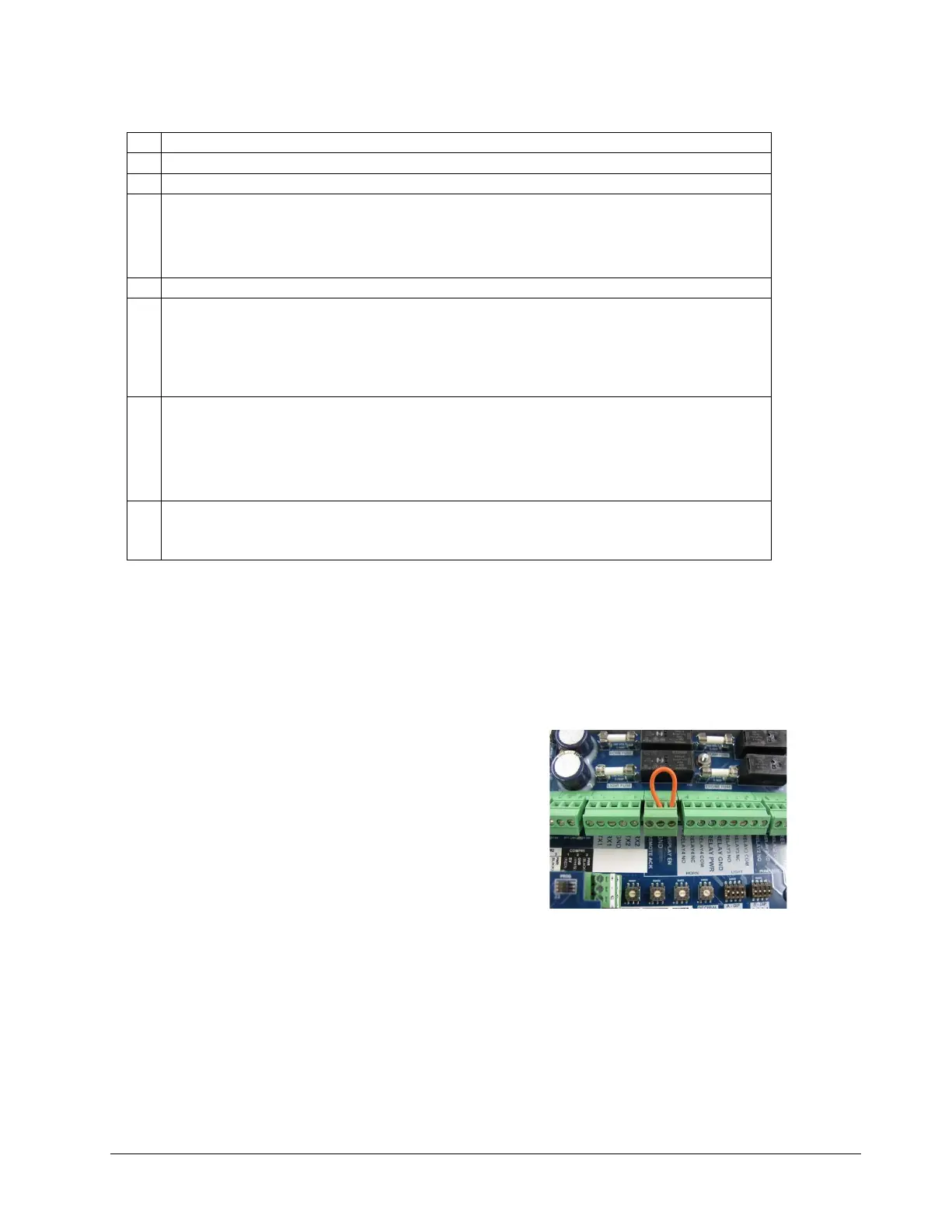
Wire from FINCH REMOTE IN: DISPLAY EN (3) to REMOTE IN: GND (2).
Optional
Remote Alarm Acknowledge push button. Follow the instructions below for the push button
installation or skip to next step if the push button is not installed.
Wire REMOTE IN: REMOTE ACK (1) to one terminal of the Normally Open push button switch.
Wire REMOTE IN: GND (2) to the other terminal of the push button switch.
Optional Horn. Follow the instructions below for horn installation or skip to next step if the horn is
not installed.
I. Wire from RELAY 3-4: RELAY PWR (4) to RELAY 3-4: RELAY4 COM (3).
II. RELAY 3-4: RELAY4 NO (1) to HORN (+)
III. RELAY 3-4: RELAY GND (5) to HORN (–)
Tighten all terminal screws; both wired and unused. The screws may loosen and fall out due to
vibration if not secured. Loose metal hardware inside the enclosure may cause permanent
equipment damage.
2.5.2 Mount the FINCH II-W Display
a) Attach the mounting tabs to the back of the FINCH II-W display.
b) Mount the display, ensuring that the unit is:
- Installed in a location that does not exceed Class 1, Div. 2 hazardous area classification.
- Mounted in a protected area, shielded from wheel spray and stones.
- Not operated in temperatures less than -40C and greater than +65.
2.5.3 Enable Remote Display
a) To enable the display to stay ON while in use, access
the FINCH II-W circuit board and connect DISPLAY EN
and GND using a jumper wire as shown.
Figure 2-5-3, Connect the Jumper wire
 Loading...