EasyManuals Logo

Titan Logix FINCH II User Manual

Default Icon
60 pages
To Next Page IconTo Next Page
To Previous Page IconTo Previous Page
Page #16 background imageLoading...
Page #16 background image
FINCH II Installation & Operation Manual
TPM 010, Rev 7.0
www.titanlogix.com Pg. 16
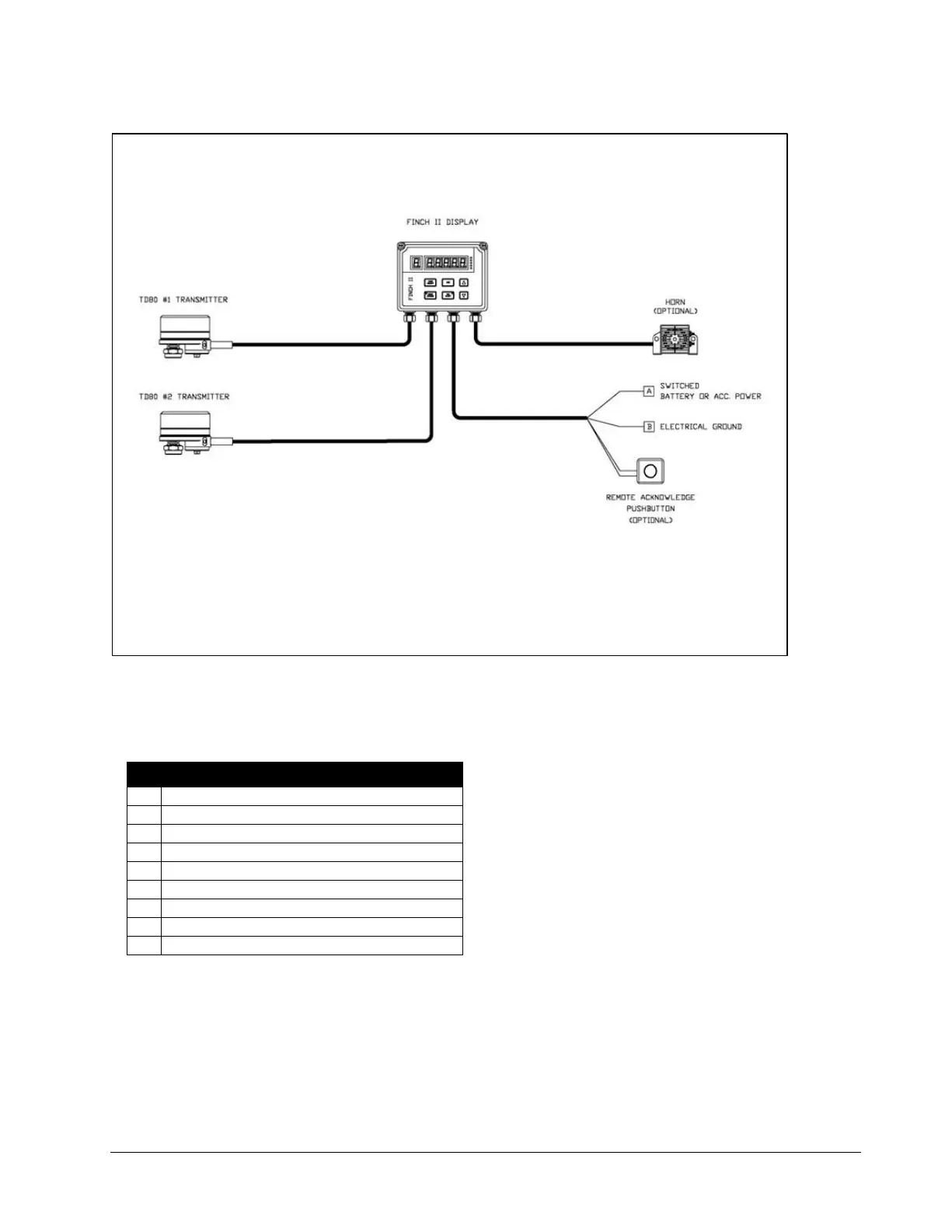
Figure 2-7: Dual TD100 Wiring Diagram for FINCH II External Display
2.6 Multi Compartment Installation (FINCH II-6W)
FINCH II-6W Installation Overview
Mount the FINCH II-6W in a suitable location
Enable remote display
Connect TD100 to FINCH 6-W
Connect to vehicle power
Connect to compartments 1 & 2
Connect to compartments 3 & 4
Connect to compartments 5 & 6
Connect to RCM
Complete the installation
2.6.1 Mount the FINCH II-6W
i) Attach the mounting tabs to the back of the FINCH display.
ii) Mount the display, ensuring that the unit is:
Installed in a location that does not exceed Class 1, Div. 2 hazardous area classification.
Mounted in a protected area, shielded from wheel spray and stones.
Not operated in temperatures less than -40°C or greater than +65°C.

Table of Contents

Questions and Answers:

Question and Answer IconNeed help?

Do you have a question about the Titan Logix FINCH II and is the answer not in the manual?

Titan Logix FINCH II Specifications

Power IconPower
power8-30 VDC
current consumption300mA at 12V
fuse ratings5A (HORN, LIGHT, PUMP/AUX and ENGINE/AUX), 10A (RELAY MAIN)
relay ratings3.3A Max on any individual relay, 6.6A Max across all 4 relays
Operating Environment IconOperating Environment
ambient temperature range40°C to +65°C
humidityRH 95% max
altitude2000 m
Communications IconCommunications
communicationsRS-232, TD100 SVBus

Related product manuals