FINCH II Installation & Operation Manual
TPM 010, Rev 7.0
www.titanlogix.com Pg. 5
1 Introduction
1.1 About This Manual
This document will describe the recommended procedure for installing a FINCH II Display. A Titan Logix system
must be installed and operated in accordance with the details described in the Titan Logix manuals, application
notes and all other relevant publications.
- This Manual (TPM010) is specific to the FINCH II Installation and Operation.
- For complete information on the TD100, please refer the TD100 Product Manual, TPM 057.
- For complete information on the RCM, please refer to the RCM Product Manual, TPM 007.
1.2 Disclaimer
The information in this document is subject to change without notice. Titan Logix Corp. makes no
representations or warranties with respect to the contents hereof.
Only qualified personnel familiar with the installation and operation of this equipment should
install, adjust operate, or service this equipment. Failure to observe these instructions and
applicable safety and electrical regulations could result in bodily injury or loss of life.
Only replace with sand filled fuses of same type and rating.
EXPLOSION HAZARD – Substitution of components may impair suitability for Class 1, Division 2.
EXPLOSION HAZARD – Do not connect or disconnect equipment or replace fuse unless power has
been switched off and / or the area is known to be non-hazardous.
EXPLOSION HAZARD – Batteries must only be changed in an area known to be non-hazardous.
To maintain a Class 1, Division 2 rating, each relay must only be supplied with
8-30VDC / 3.3A max transient protected power.
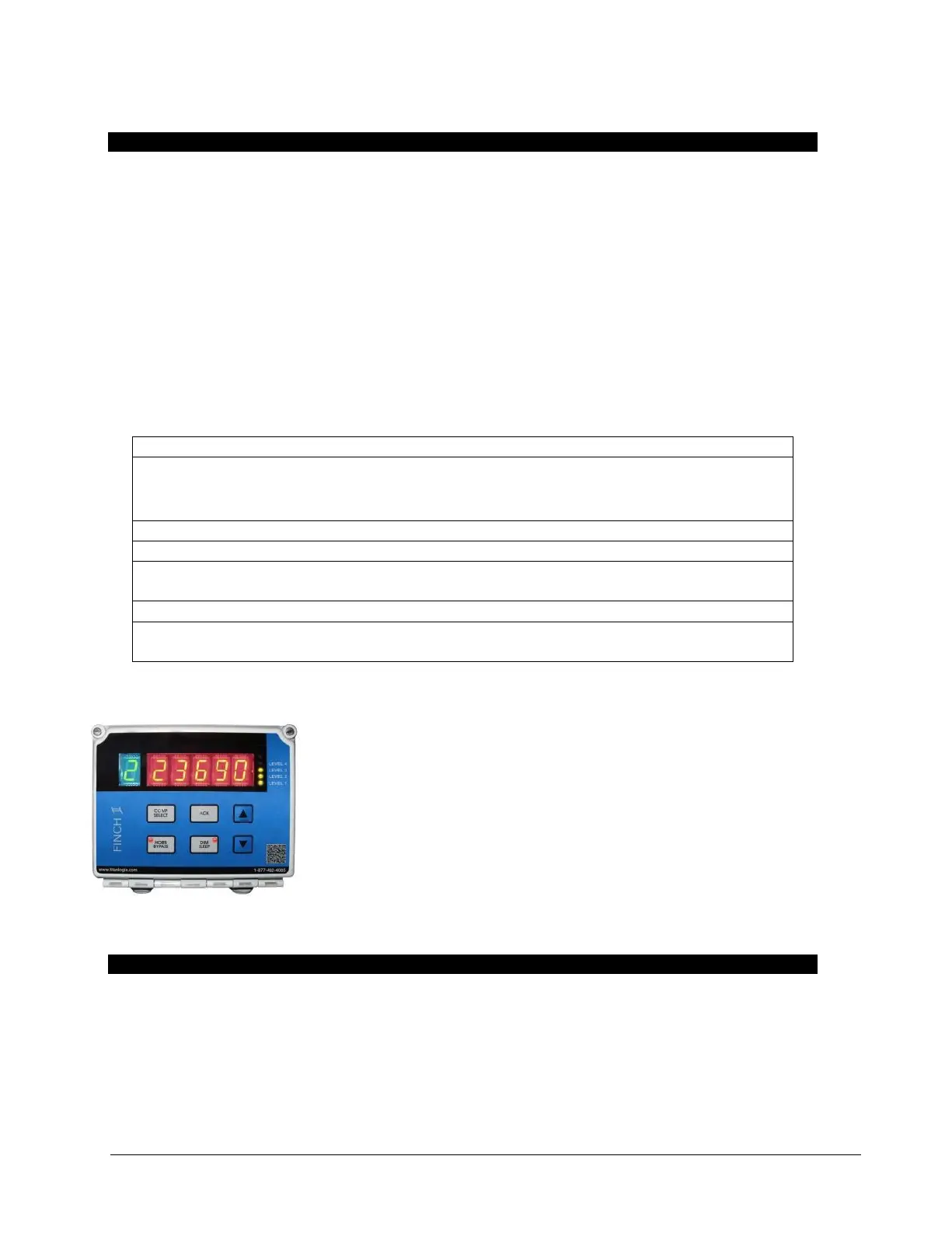
1.3 FINCH II
The FINCH II Display is weather-proof device for internal or external use.
It provides bright LED numeric display of volume information, alarms, and
system error codes from the TD80 and the TD100 transmitter. Various alarm
and error conditions are detected by the transmitter and display. These alarm
states control four internal relays for alarming, high level shutdown and low-
level prevention.
The FINCH II contains high power relays to directly control a bottom loading
solenoid valve or control of an onboard loading pump.
- FINCH II-W provides Rack control (RCM)support for 1 or 2 compartments.
- FINCH II-6W provides Rack control (RCM) support for up to 5 compartments.
2 Installation
2.1 Pre-Installation Requirements
1. When choosing a location to install the Titan Logix system, the following guidelines must be followed:
- Appropriate industry, national, provincial/state, and local codes.
- Fuses and components are appropriate for the area classification.
2. The tank is completely drained of liquid and vapour free.
3. No drilling or welding to the tank and frame without first consulting with the tank manufacturer.
4. This manual will provide information about:
 Loading...