FINCH II Installation & Operation Manual
TPM 010, Rev 7.0
www.titanlogix.com Pg. 12
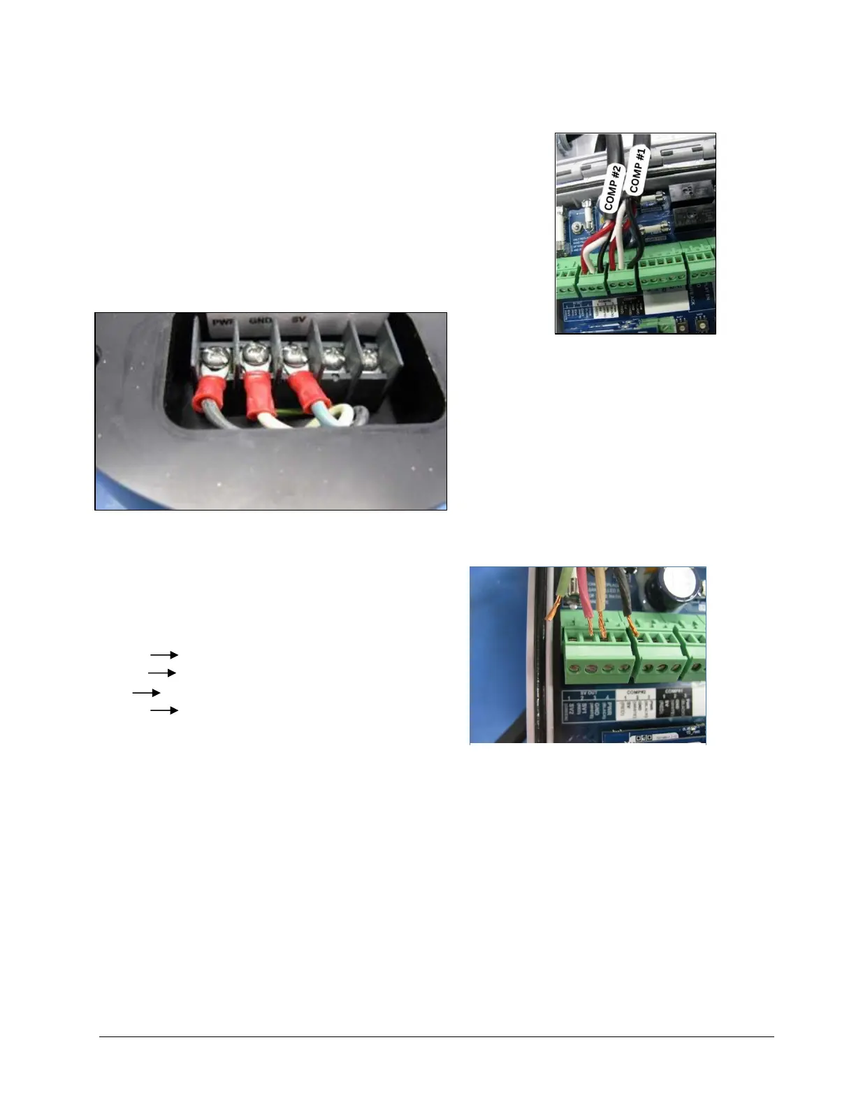
2.5.6 Connect to Compartments 1 & 2
a) Install wire harness from TD100 on Compartment 1 through a gland to
COMP #1 following the color sequence as shown in the picture.
b) Install wire harness from TD100 on Compartment 2 through a gland to
COMP #2 following the color sequence as shown in the picture.
.
2.5.7 Connect the RCM (Optional)
Make the following connections from the 4 wires on the RCM
wiring harness to SV out terminal strip on the FINCH II-W.
BLACK #4 PWR
WHITE #3 GND
RED #2 SV1
GREEN #1 SV2
2.5.8 Complete the Installation
a) Close and tighten the screws of the FINCH II-W enclosure, ensuring all connections are secure before
applying power to the TD100 system.
b) Complete the programming of FINCH II-W following the steps described in FINCH II Programming and
Configuration Guide.
c) Visually confirm if the number of compartments displayed in the Finch II-W matches the number of
compartments in the truck.
d) In the event error messages are observed when applying power to the system, refer to the
Troubleshooting section of this manual.
 Loading...