- Secure all wires and cabling with clips or cable ties.
- Tighten all compression fittings.
- Refer to Figure 2-4 through Figure 2-11 within this document, for installation wiring diagrams and
instructions.
- Tighten all terminal screws; both wired and unused. The screws may loosen and fall out due to
vibration if not secured. Loose metal hardware inside the enclosure may cause permanent equipment
damage.
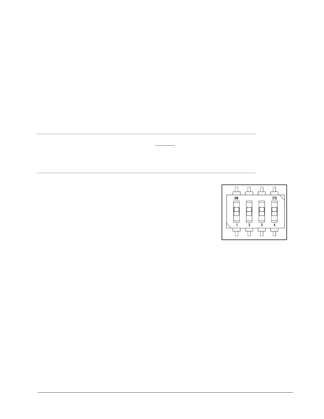
7. FINCH display switch setting and verification.
Place the following switches in the positions required for the installation. The factory settings are listed
below.
***The Rotary Switches in the FINCH II have been disabled.
As of FINCH II firmware v2.8.5, decimal point and volume units will be received from the
TD100. User will see the units and decimal point placement of the associated strapping
table.
A-DIP, ON = up, OFF= down
1 Enable Offset Calibration (Factory set to ON)
2 Enable Low Level Reading (Factory set to OFF)
3 Dual Compartment Failsafe (Factory set to OFF)
4 Reserved
B-DIP, ON = up, OFF = down.
1 Reserved
2 Set Remote Acknowledge to be an Alarm Input (Factory set to OFF)
3 Global Acknowledge Enable (Factory set to OFF)
4 Hardware Settings Lock (Factory set to OFF)
8. Confirm FINCH Fuses are installed with correct Type (Ceramic, Sand Filled) and Rating.
- HORN, LIGHT, PUMP/AUX = 5A
- RELAY MAIN = 10A (See section 11 for details on Relay Ratings).
9. Perform the TD100 Basic Operation Test
10. Verify TD100 programming information for the following:
a) Correct depth chart and units
b) Fill or Fall alarm levels.
c) HH level
d) Spill Level
11. Set the Fill and/ or Fall alarm for the required level
12. Perform TD100 System Test and Verification
13. Perform the Offset Measurement
 Loading...