* Avoid installation of the device near strong radiation e.g. TV set and PC etc.
* Maintenance should be complied with a qualified technician.
* Avoid hard shake , beating and collision, otherwise the internal exact components
maybe be damaged .
* Select the most suitable position where the monitor is located at user's eye level.
* Switch off power supply before installing.
* Keep more than 30cm away from AC power supply to avoid external interference.
* Keep it away from the water and magnetic field.
NOTE:
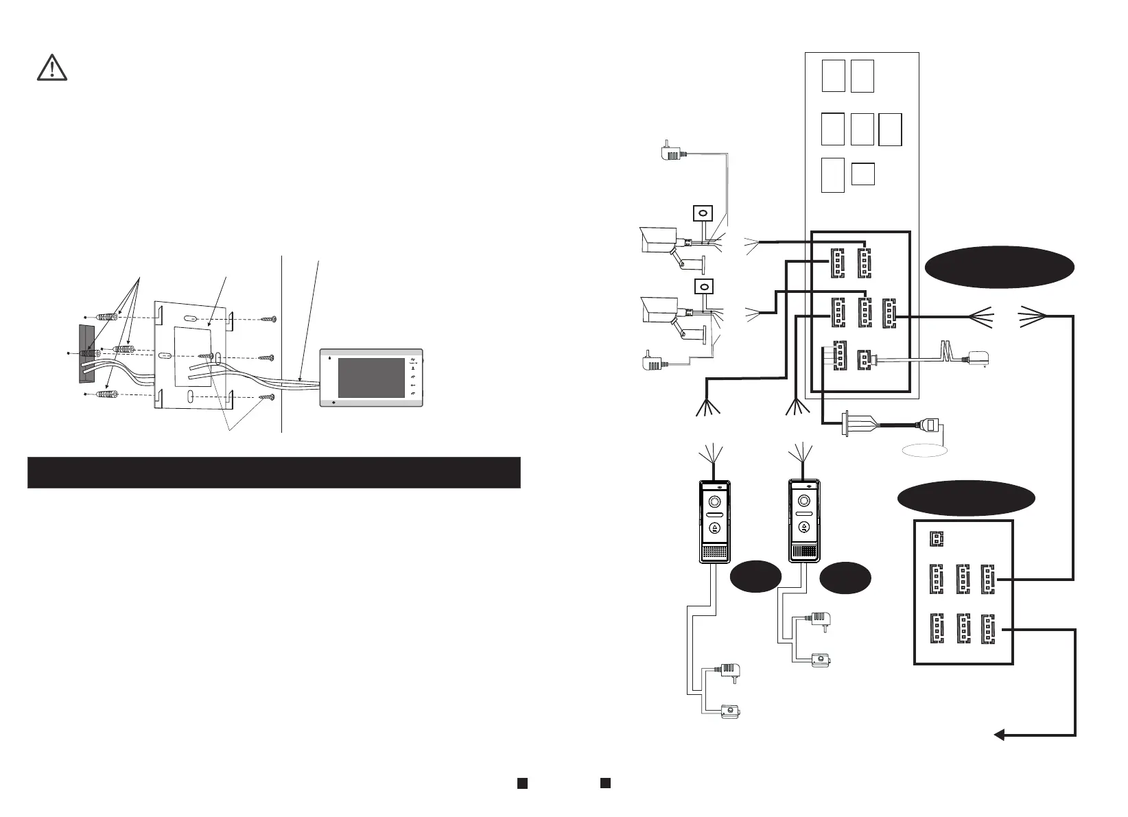
To install the indoor unit, please follow these steps as below:
1.5 Wiring Diagram
For 7'' indoor monitor, user can connect up to 2 CVBS outdoor doorbells & 2 CVBS CCTV
cameras, three extendable indoor monitor(one by one) to the corresponding interfaces by
their own’s requirement according to the following wiring diagram. The ethernet connector
is a 4 pin connector, user needs to connect a network conversion with 4 pin interface to
it(shown as below for example).
Note: 1. The indoor monitor uses an external switching power supply.
2. The CCTV cameras must use an external power supply.
(not included)
Screw anchors
cables
Bracket
Screws
Monitoring
Unlock
Talk
Hang up
1
2
G
N
D
D
C
1
2V
V
i
d
eo
A
L
M
CAM 1
CAM 2
DOOR1
DOOR2
OUT
VIDEO
GND
AUDIO
VCC
VIDEO
GND
AUDIO
VCC
VIDEO
GND
ALM
VCC
VIDEO
GND
ALM
VCC
VIDEO
DATA
GND
AUDIO
CAM 1
DOOR1
CAM 2
DOOR2
OUT
CAM1
D
C
1
2
V
A
u
d
i
o
G
N
D
V
i
d
e
o
G
N
D
DC
1
2V
Vi
de
o
A
L
M
CAM2
CAM 1
TV-out
CAM 2
IN
DOOR1
DOOR2
OUT
VIDEO
DATA
GND
AUDIO
next Slave
IP Indoor Monitor
Indoor monitor
AC/DC power
adapter
for unlocking
(not included)
AC/DC
electric lock
(not included)
DOOR2
A
L
M1
A
L
M2
D
C
1
2
V
A
u
d
i
o
G
N
D
V
i
d
e
o
AC/DC power
adapter
for unlocking
(not included)
AC/DC
electric lock
DOOR1
AC/DC power
adapter for
camera
(not included)
AC/DC power
adapter for
camera
(not included)
Rx+
Rx-
Tx
-
T
x
+
LAN
Internet
TX+
TX-
RX+
RX-
LAN
LAN
GN
D
VCC
DC 12V
DC 12V
External switching
power supply DC 12V
9
10

 Loading...