GENERAL PURPOSE BROADCAST EXPANSION FUNCTIONS
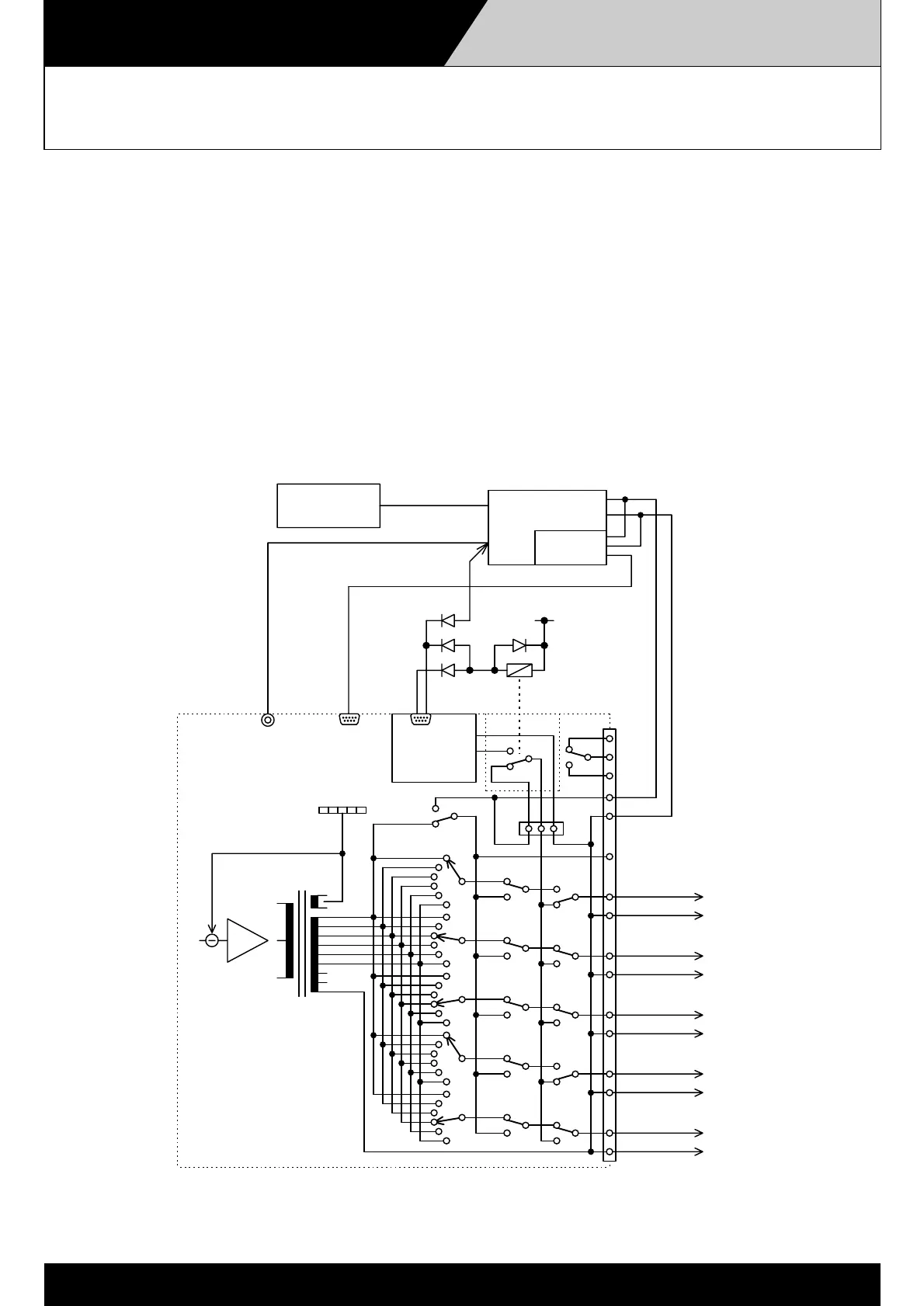
Connection When Using Both Standby and
Quasi-Dual-Origination Amplifiers
4-5-10
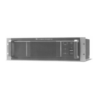
YA-1000A
VP1120/1240
T
Level meter
N1
1
Power Amp.
Zone vol.
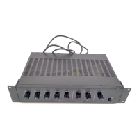
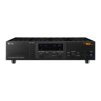
SV-200M
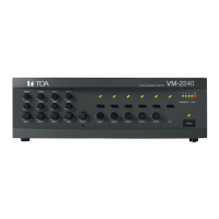
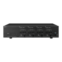
VM-2120/2240
PRE OUT
p15 Fail.
PROGRAM IN
ZONE 5
ZONE 4
ZONE
ZONE 2
ZONE 1
100V OUT
OUT
PRIORITY IN
BGM Source
p12 Amp. fail.p13 Busyindicator ctrl.
Priority remote
RY
DC V
NC
NO
COM
The following system permits use of both the BGM amplifier for quasi-dual-origination broadcasts and
the standby amplifier.
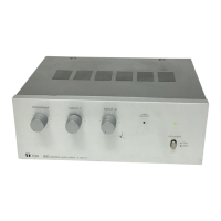
Prepare a standby amplifier (here, a VP-1120 or VP-1240) with the same output power rating (wattage) as that
of the VM amplifier. Place a relay between the SV-200M's CN3 connector and the VM amplifier's RY PCB 1003
circuit board, and control the relay by means of the Surveillance I/O connector's Pin 12 (Power Amplifier Failure)
and Pin 13 (Setting/Checking Busy). Details are explained in 4-5-9 Operation When Using Both the Standby and the
Quasi-Dual-Origination Amplifiers section.
NOTE: The amplifiers cannot be modified not to distribute external BGM to the specified zones.
 Loading...