GENERAL PURPOSE BROADCAST INPUT
Input 1-3 (MIC/LINE)
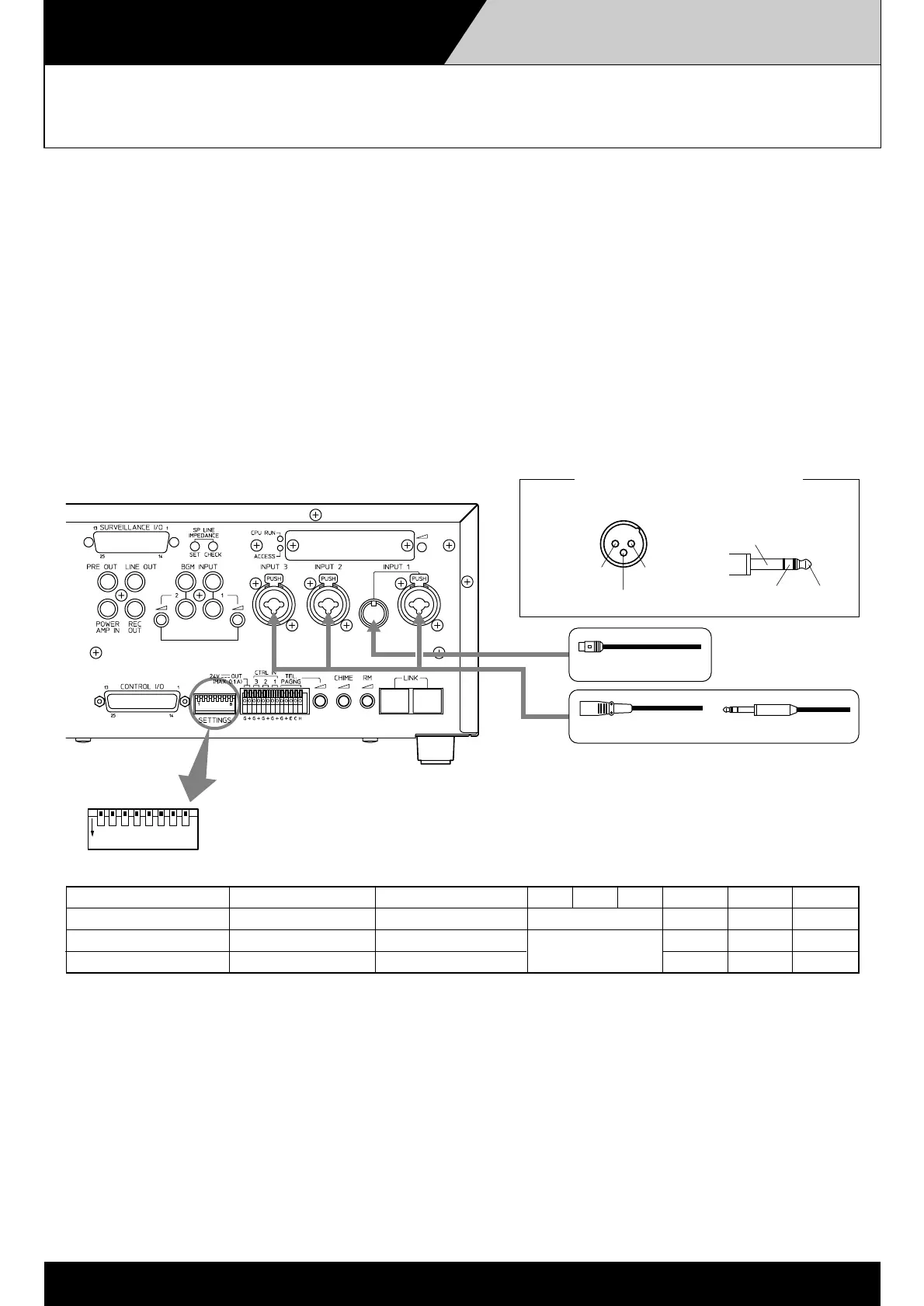
4-1-1
SETTINGS
All switches No. 1 – 8 are factory-preset to the OFF position.
12
ON
345678
Switch No.
12345678
Function
Telephone PagingPhantom Power*
1
Chime Selection Input 3 Input 2 Input 1
OFF (Up position)
OFF Chime ON Mic Mic Mic
ON (Down position)
ON Chime OFF Line Line Line
See the Chime
Selection table
Simultaneously turns on or off the phantom power of Inputs
1 – 3. For the method to switch off the phantom power for the
individual Inputs 1 to 3, consult the shop from whom the unit was
purchased.
*
1
Usable connectors and plugs
• XLR type male connector • Phone plug
Pin 1: Ground
Sleeve: Ground
Pin 2: Hot
Tip: Hot
Pin 3: Cold
Ring: Cold
DIN connector
XLR type connector Phone plug
Inputs 1 – 3 can be set for a microphone signal input level ( –60 dB, 600 Ω) or a line signal input level
( –10 dB, 600 Ω) by moving the SETTINGS switch in Fig. 1 to the ON or OFF position. The three inputs also
feature Neutrik connectors that permit connection to XLR connectors and phone plugs. Furthermore,
Input 1 can also be used for DIN plugs as well.
Equipment that can be connected to these input includes:
• Dynamic microphones
• Paging microphones
• Wireless tuners
• Background music players
Fig. 1
 Loading...