SURVEILLANCE FUNCTIONS SURVEILLANCE FUNCTIONS
6-2
ZONE 15
ZONE 14
ZONE 13
ZONE 12
ZONE 11
ZONE 10
ZONE 9
ZONE 8
ZONE 7
ZONE 6
ZONE 5
ZONE 4
ZONE 3
ZONE 2
ZONE 1
EMERGENCY
FAILURE
COMMUNICATION
EV-200 FAILURE
POWER AMP FAILURE (Master)
GROUND FAULT (Zone1 – 5)
POWER AMP FAILURE (Sub)
GROUND FAULT (Zone6 – 10)
POWER SWITCH ON
DC POWER ON
AC POWER ON
INITIAL SETTING
SET/CHECK BUSY
RM-200M
RM-210
VM Master Amplifier
AC Adapter
RM-210
VM Sub Amplifier
Monitor Display
VM Sub Amplifier
Master
SV I/O
SV I/O
BGM Player
Telephone
Sensor
TIMER
Dynamic
Microphone
TEL SYSTEM
FIRE ALARM
Input 1
BGM 1
TEL Paging
Control I/O
Control I/O
Pre out
Link
Link
PA in
Master
Link
PA in
SV I/O
CNT I/O
SV-200M
SV-200M
SV-200M
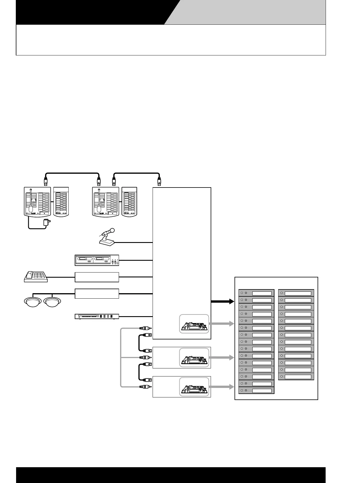
Surveillance Functions for Multiple
VM Amplifier Systems
To perform system-wide surveillance, an SV-200M unit must be installed in each amplifier.
To display surveillance results on the external indication board, connect each amplifier's SV-200M unit to a
corresponding indication board.
Note that "communication by link cable" errors cannot be displayed if the total number of sub-amplifiers and Remote Microphones within
the same system exceeds 7.
 Loading...