SURVEILLANCE FUNCTIONS SURVEILLANCE FUNCTIONS
6-4
EMERGENCY
FAILURE
COMMUNICATION ERROR
EV-200 FAILURE
POWER AMP FAILURE (Master)
GROUND FAULT (Zone1 – 5)
POWER AMP FAILURE (Sub)
GROUND FAULT (Zone6 – 10)
POWER SWITCH ON
DC POWER ON
AC POWER ON
INITIAL SETTING
SET/CHECK BUSY
ZONE 1
OPEN SHORT
MONITOR
ZONE 1
ZONE 2
ZONE 3
ZONE 4
ZONE 5
ZONE 6
ZONE 7
ZONE 8
ZONE 9
ZONE 10
ZONE 1
ZONE 2
ZONE 3
ZONE 4
ZONE 5
ZONE 6
ZONE 7
ZONE 8
ZONE9
ZONE 10
EMERGENCY
FAILURE
COMMUNICATION ERROR
EV-200 FAILURE
POWER AMP FAILURE (Master)
GROUND FAULT (Zone1 – 5)
POWER AMP FAILURE (Sub)
GROUND FAULT (Zone6 – 10)
POWER SWITCH ON
DC POWER ON
AC POWER ON
INITIAL SETTING
SET/CHECK BUSY
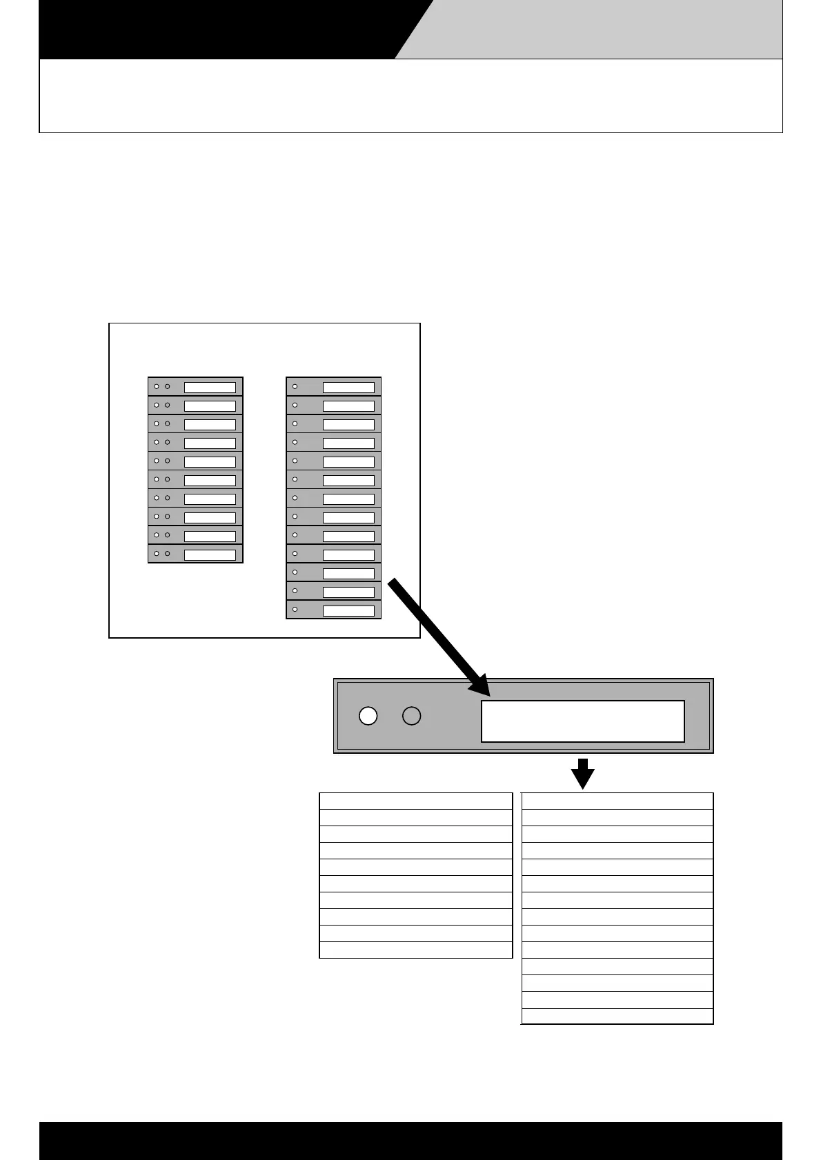
Example of a Custom-Made Panel
to Display VM Amplifier Status
An active low signal is transmitted to the custom-made indication panel from the VM amplifier's control I/O
terminal and the SV-200M installed in the VM amplifier, causing the indication panel LED to light.
(The example assumes the system consisting
of 2 linked VM amplifiers with EV-200 and
SV-200M units installed, and an RM-200M unit
expanded with an RM-210 unit.)
 Loading...