12
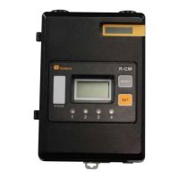
Modular Conversoin Receiver Model: R-CM
4-3-1. Caution of Input Connector Internal Circuit
● IN1 and IN2 Input terminal
㻾㻱㻿㻱㼀
㼂㼏㼏
㻸㻿㻙㻵㻺
Photo coupler
Photo coupler
EMI filter
EMI filter
Internal circuit
No-voltage contact switch
No-voltage contact switch
Connect this input terminal with a non-voltage contact switch such as LS torque wrench, push button
switch, or relay.
* Do not use any external source to supply power to the input circuit. It may cause malfunction.
4-3-2. Caution of Output Connector Internal Circuit
● OUT1, OUT2, OUT3, OUT4 Output Terminals.
・・・・
Relay
Relay
Internal circuit
OUT1
OUT4
Load
External Power
Load
External Power
Apply the rated load to the contact output. Relay rated output : DC30V 1A, AC125V 0.5A
The rated contact capacity is based on the resistance load. The steady-state current and the inrush
current may differ greatly depending on the load type. The table below shows the relation between the
typical loads and inrush currents.
Load type Inrush current
Resistance load About same as the steady-state current
Solenoid load
10 to 20 times of the steady-state current
Motor load
5 to 10 times of the steady-state current
Incandescent lamp load
10 to 15 times of the steady-state current
Mercury-vapor lamp load
About 3 times of the steady-state current
Sodium-vapor lamp load
1 to 3 times of the steady-state current
Condenser load
20 to 40 times of the steady-state current
Transformer load
5 to 15 times of as the steady-state current

 Loading...