Document Ref 942005-001 Rev 2.2 Page 2-7
Component Technical Manual TQP-HS for Fuel Dispensers
2.6 Operating Description
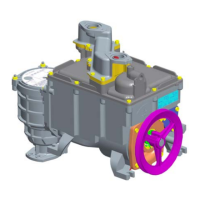
2.6.1 PUMPING, FILTRATION & BY-PASS
The fuel held in the storage tank underground is raised by the gear pump [4] and
passes through the filter [3] and the foot valve [2].
The gear pump forces the product through the vortex system [17] into the high-
pressure chamber [19].
When the flow pressure exceeds the reference pressure, adjusted by the by-pass
screw, the by-pass valve [16] opens and the excess fuel in the high-pressure
chamber [19] is channelled back to the intake. Thus, the outlet pressure is kept
constant regardless of the flow drawn off by the fuel distribution hose(s).
2.6.2 ABOVE GROUND TANK APPLICATIONS
The Tokheim suction pumps have been specifically designed to work in conjunction
with underground tanks where the fuel level inside varies between 0.5 and 4
meters below the pump shaft.On suction pumps, minimal vacuum held on the
suction line must be greater than 80mB to allow normal operation of pump and
air elimination device.
Should dispensers be connected to ‘above ground tanks’ (partial or total), special
care must be taken to avoid siphoning storage tanks via air vents or in case of
leak/accident on connecting pipes, by using properly installed anti-siphon valves.
Please refer to state of the art equipment currently available and compliant with
local/national rules/requirements. Eg: OPW anti-siphon valves.
Recommendation is to install this device at its highest point of piping, to allow for
maximum protection.
Note : Tokheim cannot be held responsible for any equipment failure,
accident or injury should these instructions not be followed.
2.6.3 AIR SEPARATION
The flow is channelled tangentially into the vortex where the shape of the inlet
[17] imparts a helical movement to the flow producing a centrifugal effect.
Due to the strong centrifugal effect, air/vapour is extracted from the flow with
the heavier liquid product molecules in the flow forced by the centrifugal pressure
towards the outside walls of the vortex channel and then directed away to the
high-pressure chamber. The lighter air/vapour molecules remain trapped in the
centre of the vortex channel and are then directed away through the vortex tube
and vortex valves into the recovery chamber.
The purpose of the vortex valves is to regulate the flow at different pressures.
The pressure depends on the amount of air in the flow. After the vortex valves,
the particles move into the recovery chamber [10].
Important!
 Loading...