Page 9
STEP 10
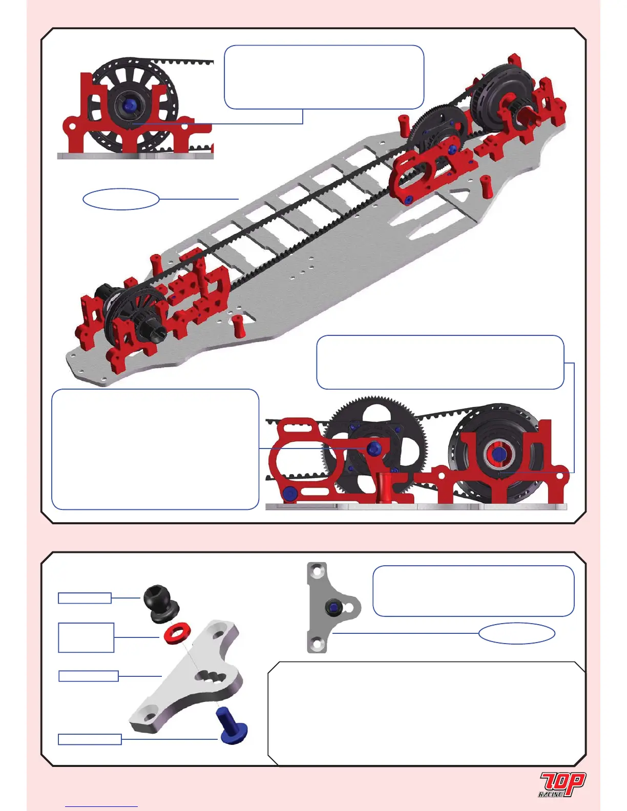
FINISHED
STEP 10 (con’d)
TRANSMISSION (con’d)
Rubber Foam
FRFR
BAG F TC-PCHC008-1 Camber Link Plate (2.5mm) x 2 x 2 x 2 x 2
AW-S250RD-1 3 x 5.5 x 2.5mm Collar x 2
AW-S150RD-1 3 x 5.5 x 1.5mm Collar x 2
AW-S200RD-1 3 x 5.5 x 2.0mm Collar x 2
AW-S200RD-1 3 x 5.5 x 2.0mm Collar x 2
PA-HBS003-1 5.3mm Ball (Steel) x 2 x 2 x 2 x 2
PA-BM0308BK-1 M3x8mm Button Head Screw x 2 x 2 x 2 x 2
Note: Pay attention to the initial orientation
of the bearing cam as shown. Rotate the
cam forward to loosen the front belt and
backward to tighten it. You might have to
loosen it for your fi rst 2 runs with the car.
UPPER CHASSIS
STEP 11 (Make 2 x Front & 2 x Rear)
STEP 11F, R
FINISHED
TC-PCHC008-1
AW-SxxxRD-1
See parts table
for collar size
PA-HBS003-1
PA-BM0308BK-1
Note: Pay attention to the initial position
of the center drive assembly. It is set at its
lowest. The position should be heightened
when using a larger spur gear to avoid touching
the main chassis. If you choose to heighten
the position of the center drive assembly, pay
attention to whether the front drive belt touches
your pinion. If that’s the case, you would have
to use a larger pinion or spur gear, or choose
not to heighten the assembly too much.
Note: Pay attention to the initial orientation of
the bearing cam as shown. Rotate the cam backward to
loosen the rear belt and forward to tighten it. You might
have to loosen it for your fi rst 2 runs with the car.
Note: This is the initial setup for the
camber ball stud position of the rubber asphalt
edition. Refer to the foam standard setup in
Page 30 for the foam carpet edition.
 Loading...