Page 5
CENTER DRIVE
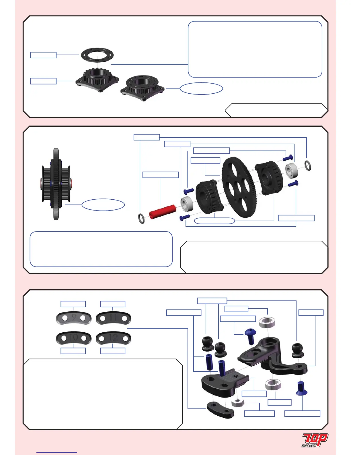
STEP 06
STEP 08
Rubber Foam
BAG C Mold I-01-1 Bell Crank x 1 x 1
Mold I-02-1 Bell Crank Extension x 1 x 1
Mold I-04-1 BCE Insert #10 x 1
Mold I-05-1 BCE Insert #11 x 1
MR85ZZ-1 5 x 8 x 2.5mm Bearing x 2 x 2
PA-BM0306BK-1 M3x6mm Button Head Screw x 1 x 1
PA-FN00M3-1 M3 Nut x 1 x 1
PA-HBS003-1 5.3mm Ball (Steel) x 3 x 3
PA-SS0308BK-1 M3x8mm Set Screw x 2 x 2
PA-CM0306BK-1 M3x6mm Countersunk Screw x 1 x 1
BAG C Mold L-07-1 Center Shaft Spacer x 2
MR105ZZ-1 5 x 10 x 4mm Bearing x 2
SG-K64100-1 100T 64P Spur Gear x 1
TC-PDT005RD-1 Centre Pulley Shaft x 1
PA-SCM205BK-1 M2x5mm Chess Head Screws x 4
STEP 07
BAG C Mold L-02-1 20T Pulley x 2
Mold L-03-1 20T Flange x 2
STEERING CRANK
STEP 07
FINISHED
Mold L-07-1
MR105ZZ-1
SG-K64100-1
PA-SCM205BK-1
TC-PDT005RD-1
from STEP 06
PA-SCM205BK-1
Mold L-02-1
Mold L-03-1
STEP 06
FINISHED
Note: Apply a small amount of instant glue in
betwwen the 20T pulley and 20T fl ange. Be careful
not to let the glue go onto the teeth of the pulleys.
The fi tting between Mold L-03-1 and Mold L-02-1 are
purposefully designed to have a tight fi tting. Be very
carefull when applying instant glue at the contact edge
AFTER the 2 parts are locked together.
Make a total of 2 sets for this step.
Mold I-03-1
Mold I-06-1
Mold I-04-1
Mold I-05-1
PA-HBS003-1
PA-SS0308BK-1
PA-BM0306BK-1
MR85ZZ-1
MR85ZZ-1
Mold I-02-1
Mold I-01-1
PA-FN00M3-1 PA-CM0306BK-1
Note: Slightly ream out both sides of the four 3mm
holes on the spur gear where the 20T pulleys go into,
because plastic burr may exist at these locations. Use
ONLY T.O.P. and Xenon spur gears. These are the ones
that fi t best with our 20T pulleys.
 Loading...