8 2031005680 Rev. C, 06/2016
6. ADJUSTMENTS
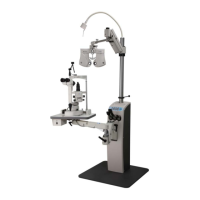
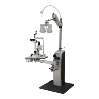
The refractor and slit lamp arms may require adjustment depending upon the weight of the
instrument in use.
6.1 Refractor and Slit Lamp Arm
6.1.1 Counterbalance Adjustment
To adjust the counterbalancing of the instrument arm, remove the black plastic panel
located at the instrument end of the arm by unscrewing the (2) round-head Hex screws,
and then lock the instrument arm at its maximum elevated position.
Underneath the black cover is castellated (slotted) nut. To adjust the refractor arm,
insert the end of a 5/32 Hex wrench into the castellated (slotted) part of the nut. The
arm counter-balancing spring tension is adjusted by turning the nut in the appropriate
direction. (NOTE: Follow the same steps for adjusting the optional middle arm, but
use a 3/16 Hex wrench instead.)
Turning the nut clockwise, as viewed from the instrument end of the arm, increases the
counterbalance force. Counterclockwise rotation loosens the counterbalance force.
6.1.2 Brake Adjustment
NOTE: This section is for Refractor Arm only.
At the instrument end of the arm there is a handle, which activates the brake. This
handle locks the three arm functions simultaneously: the instrument end of the arm,
the pole end of the arm, and the counterbalance mechanism. Each of these three
brakes can be adjusted independently of the others.
At the instrument and pole ends of the arm are two (2) Hex set screws. The small
setscrew adjusts the brake force. To adjust the brake, lock the handle and turn the
screw 1/4 turn. Clockwise rotation increases the braking force and counterclockwise
rotation decreases the braking force.
6.1.3 Counterbalance Brake Adjustment
NOTE: This section is for Refractor Arm only.
In instances where the brake is not restraining vertical movement, the
counterbalancing brake will need to be adjusted. The counterbalancing brake
adjustment is located on the diagonal arm (refer to Figure 5). The arm will have three
(3) black screws with caps on one end and a small opening underneath the middle
black screw.
Lower or raise the arm slowly until the small Hex screw is aligned with the access
hole in the arm housing. Once the Hex screw has been aligned, activate the brake, and
then turn the screw clockwise approximately 1/4 turn. (NOTE: When activating the
handle, place your thumb between the handle and the inner wall when tightening the
small Hex screw. Next fully activate the brake and press down on the auxiliary arm.
If the resistance is inadequate, repeat the above procedure and turn the small Hex
screw another 1/4 turn.)