2031005680 Rev. C, 06/2016 1
2. NOMENCLATURE
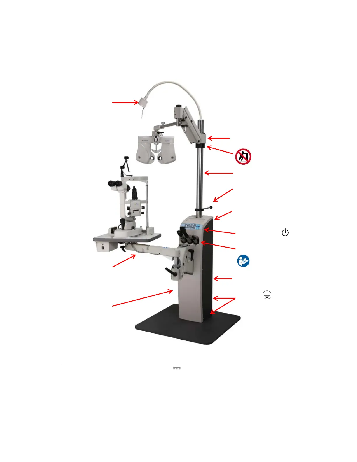
2.1 IS-5500 Instrument Stand Main Components
Figure 1 shows the primary components and key features of the IS-5500 Instrument Stand.
Use this figure as a reference only.
Figure 1: IS-5500 Instrument Stand
*NOTE:
1. Label: INDIRECT RATED NOT TO EXCEED: 14V 3A
2. Labels: Serial Label and ETL Label
3. SL Label placed around cable: SL NOT TO EXCEED 120V ~60HZ 1.0A
4. “Do Not Push” Labels (QTY: 2) placed on left and right sides of the black ring, to be visible to operators and patients:
Pushing is prohibited.
5. Grounding Labels (QTY: 2) placed on floorplate and on back cover next to grounding points (inside Base Assembly)
6. Warning Label on MSO (inside Base Assembly)
7. High Voltage Label on Tube bracket, above Circuit Board (inside Base Assembly)
(SL Label, See Note 3)
(Label, See Note 1)
(See Notes 6-7)
(See Notes 2 & 5)