g014840
Figure52
1.Bedbar-adjustingscrew
4.Rotatethereelsothatabladecrossesthe
bedknifeedgebetweentherstandsecond
bedknifescrewheadsontherightsideofthe
cuttingunit.
5.Insertthe0.05mm(0.002inch)shimbetween
themarkedbladeandthebedknifeedgeat
thepointwherethemarkedbladecrossesthe
bedknifeedge.
6.Turntherightbedbar-adjustingscrewuntilyou
feellightpressure(i.e.,drag)ontheshimby
slidingitside-to-side(Figure52).
7.Removetheshim.
8.Fortheleftsideofthecuttingunit,slowlyrotate
thereelsothattheclosestbladecrossesthe
bedknifeedgebetweentherstandsecond
screwheads.
9.Repeatsteps4through7fortheleftsideofthe
cuttingunitandleftbedbar-adjustingscrew.
10.Repeatsteps5through7untillightdragis
achievedonboththerightandleftsidesofthe
cuttingunitutilizingthesamecontactpoints.
11.Toobtainlightcontactbetweenthereeland
bedknife,turneachbedbar-adjustingscrew
clockwise3clicks.
Note:Eachclickturnedonthebedbar-adjusting
screwmovesthebedknife0.018mm(0.0007
inch).Clockwiserotationmovesthebedknife
edgeclosertothereelandcounterclockwise
rotationmovethebedknifeedgeawayfromthe
reel.
12.T estthecuttingperformancebyinsertingalong
stripofcuttingperformancepaperbetweenthe
reelandbedknife,perpendiculartothebedknife
(Figure53).Slowlyrotatethereelforward;it
shouldcutthepaper.
g007602
Figure53
Note:Ifyouseeexcessivecontact/reeldrag,it
willbenecessarytobacklap,facethefrontof
thebedknife,orgrindthecuttingunittoachieve
thesharpedgesthatarenecessaryforprecise
cutting.
AdjustingtheHeight-of-Cut
1.Verifythattherearrollerislevelandthatthe
bedknife-to-reelcontactiscorrect.Tipthe
machinebackonthehandletoexposethefront
andrearrollersandthebedknife.
Important:Donottipthemachineatan
anglegreaterthan25°.Tippingthemachine
beyond25°leadstooilleakingintothe
combustionchamberand/orfuelleakingout
ofthefuel-tankcap.
2.Loosenthelocknutsthatsecuretheheight-of-cut
armstotheheight-of-cutbrackets(Figure54).
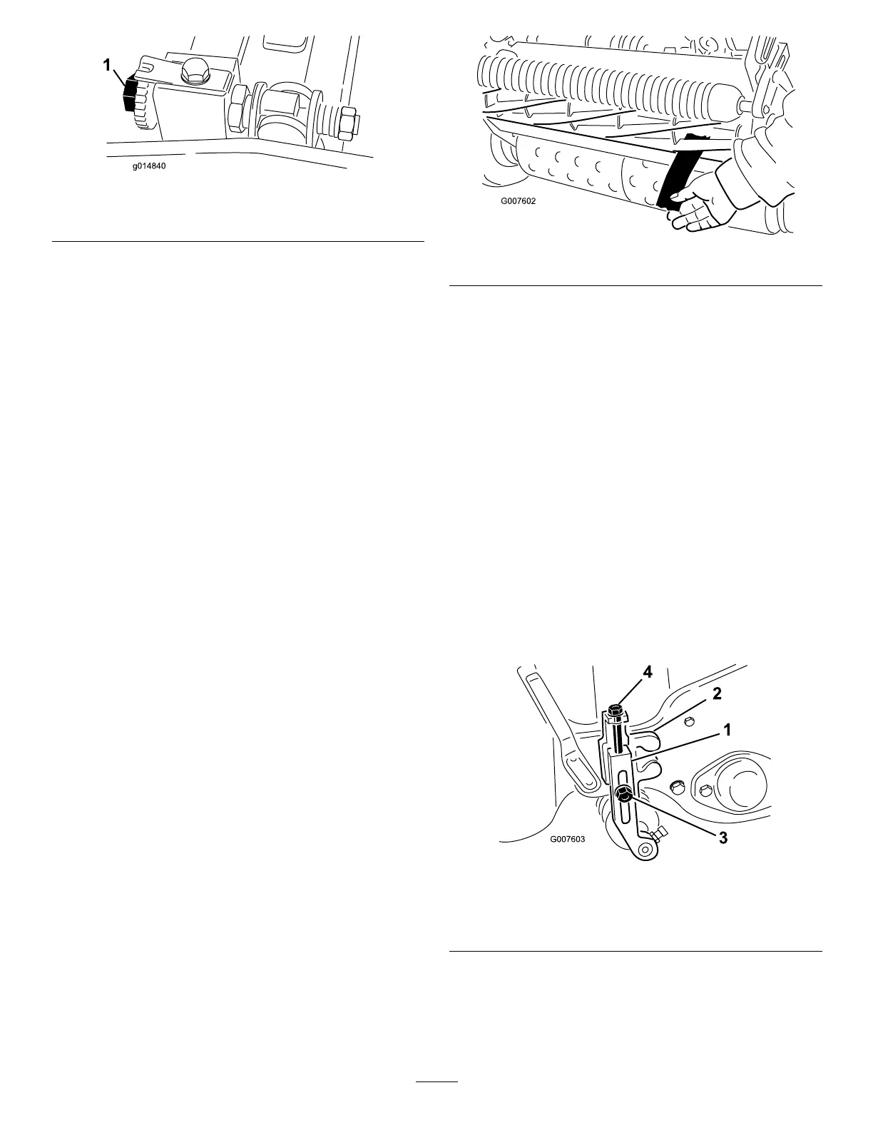
g007603
Figure54
1.Height-of-cutarm
3.Locknut
2.Height-of-cutbracket
4.Adjustingscrew
3.Loosenthenutonthegaugebar(Figure55)
andsettheadjustingscrewtothedesired
height-of-cut.Thedistancebetweenthebottom
ofthescrewheadandthefaceofthebaristhe
heightofcut.
37