Setup
MediaandAdditionalParts
Description
Qty.
Use
Operator'sManual
1
Readbeforeinstallingandoperatingcuttingunit
Partscatalog1
Usetoreferencepartnumbers
InstallingtheFrontRoller
Thecuttingunitisshippedwithoutafrontroller.Installthe
rollerusingtheloosepartssuppliedwiththecuttingunitand
installationinstructionsincludedwiththeroller.
UsingtheCuttingUnitProp
Wheneverthecuttingunithastobetippedtoexposethe
bedknife/reel,propuptherearofthecuttingunittomake
surethenutsonthebackendofthebedbaradjustingscrews
arenotrestingontheworksurface(Figure3).
Figure3
1.Prop(notprovided)2.Bedknifeadjustingscrew
nut(2)
AdjustingtheBedknifetothe
Reel
Note:Usethisprocedureaftergrinding,backlapping,or
disassembly.Itisnotintendedasadailyadjustment.
1.Positionthecuttingunitonaat,levelworksurface.
2.Tipthecuttingunittoexposethebedknifeandthe
reel.Makesurethenutsorthebackofthebedbar
adjustingscrewsarenotrestingonthework
surface(Figure4).
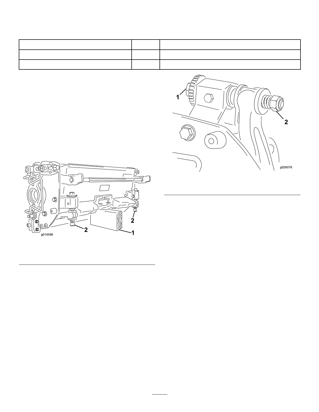
Figure4
1.Bedknifeadjustingscrew
2.Nut
3.Rotatethereelsothatabladecrossesthebedknifeedge
betweentherstandsecondbedknifescrewheadson
therightsideofthecuttingunit.
4.Putanidentifyingmarkonthebladewhereit
crossesthebedknifeedge;thiswillmakesubsequent
adjustmentseasier.
5.Insertthe.05mm(0.002inch)shimbetweenthe
markedbladeandthebedknifeedgeatthepointwhere
themarkedbladecrossesthebedknifeedge.
6.Turntherightbedbaradjustingscrewuntilyoufeel
lightpressure(i.e.drag)ontheshimbyslidingit
side-to-side.Removetheshim.
7.Fortheleftsideofthecuttingunit,slowlyrotatethe
reelsothattheclosestbladecrossesthebedknifeedge
betweentherstandsecondscrewheads.
8.Repeatsteps4through6fortheleftsideofthecutting
unitandleftbedbaradjustingscrew.
9.Repeatsteps5and6untillightdragisachievedon
boththerightandleftsidesofthecuttingunitutilizing
thesamecontactpoints.
Thebedknifeisnowparalleltothereel.
10.Toobtainlightcontactbetweenthereelandbedknife,
turneachbedbaradjustingscrewclockwise3clicks.
Note:Eachclickturnedonthebedbaradjusting
screwmovesthebedknife0.018mm(0.0007inches).
Clockwiserotationmovesthebedknifeedgecloser
4