InstallationInstructions
1.Stopengine,waitforallmovingpartstostop,
engagetheparkingbrakeremovethekey,and
disconnectthenegativebatterycable.
2.Removeandretaintherearcushion.
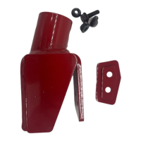
3.Attachthefoammarkernozzletothenozzle
bracketusingtwozipties.Removeandretain
thetopnutontheleftspraynozzle.Alignthe
holeinthenozzlebracketoverthetopofthe
leftspraynozzle.SecurethebrackettotheLH
sprayboomusing1/4-20x1/2inchboltandnut
asFigure3.Reinstallthenozzlenutandtorque
to18-22in-lb(2-2.5N-m).Repeatthisstepto
installthefoammarkernozzleontheRHside.
g416053
Figure3
1.1/4-20x1/2inchbolt4.Leftspraynozzle
2.Nozzlebracket
5.1/4-20inchnut
3.Foammarkernozzle6.Ziptie
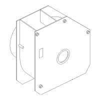
4.Placethetankassemblyontotheleftspraytank
andsecuretoleftsideofthecontroltowerusing
two5/16-18x1inchscrewsandtwo5/16inch
nylocangednutsasshowninFigure2.
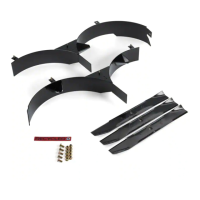
5.Installthesprayhosefromthiskitontothefoam
markertankbacktting.Looselyroutethehose
downwardalongtheleftsideofthemachine.
Routethehoseundertheframeandtowardsthe
centeroftheboomasshowninFigure4.
g412381
Figure4
1.Routinghoseonleftside
4.Righthose
2.Teetting5.Routehoseunderframe
3.Lefthose
6.Withthehoselooselydrapedoverthefront
boom,cutthehosewhereitalignsinthe
approximatecenteroftheboom.
7.Laythenewlycuthoseacrosstheboomtoboth
headnozzlesandcutitwherethefoammarker
tankhosewouldintersectinthecenter.Install
theteettingintothehosesasshowninFigure
4.
Cuttolengtheachhoseattheheadnozzleand
thenattachtothenozzle.
8.Looselysecurethehoseswithzipties(reference
Figure2).
9.Usingthecontrolpanelasaguide,carefully
cutouttheswitchopeninginthedecalthatis
locatedtotherightofthesprayswitch.
g412355
Figure5
1.Sprayswitch2.Switchopening
10.Placetheswitchonthetopsideofthecontrol
panelandorientitsimilartotheexistingswitch.
Carefullysnaptheswitchintothecutout.Route
thefoammarkerharnessunderneaththe
6