panelandconnecttheswitch.Makesurethe
connectorsarefullyinsertedontotheterminals.
11.Cleanthesurfaceoftheexistingdecal.Orient
thedecaltomatchthesymbolsofthespray
systemswitch.Installthedecalontherightside
ofthenewlyinstalledswitch.
12.Installtheharness.
A.Locatetheconnectorlabeled“accessory
port”onthemachinemainharnessunder
thecontrolpanel.Removetheconnector
capandplugintheaccessoryrelayharness.
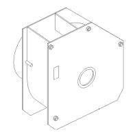
B.Placetherelayontheinsideoftheframe
asshowninFigure6andsecurewiththe
plasticplug.Connectthefoammarker
harnesstotheaccessoryrelayharnessand
routethefoammarkerharnesstowardsthe
leftfrontcornerofthecontroltower.
C.Locatetheconnectorlabeled“foammarker”
nearthelower,front,leftsideofthecontrol
towerandpluginthefoammarkerharness.
Finishroutingtheharnessuptheoutsideof
thetowertothefoammarkerandpluginto
thefoammarkerunit.
g412358
Figure6
1.Plasticplug3.Accessoryharness
2.Relay4.Ziptie
13.Useziptiestosecuretheaccessoryharness
awayfromothercomponents.
14.Tightenthehosezipties.
15.Reconnectthenegativebatterycable.
16.Addpurecleanwatertothetwogallontank.
17.TurntheignitionkeytoONandthenoperatethe
spraysystemandcheckforleaks.Repairall
leaksbeforereturningthesprayertoservice.
18.Reinstalltherearcushion.
OperatingInstructions
1.WiththekeyswitchOFFandthefoammarker
switchOFF ,thefoammarkershouldnotbeON.
2.TurnthekeyswitchON.Thefoammarker
switchshouldtogglethetankoffandon.The
tankshouldbeoffwhentheswitchisdepressed
downonthe“O”sideofthedecal.Ifthefoam
markeroperatesoppositeofthis,removeand
rotatetheswitch180degreesandreinstall.
WiththeswitchintheONposition,press
andholdthefootbuttontoturnonthespray.
Releasingthebuttonturnsoffthespray.
decal142-8574
Figure7
1.On3.Spraypump-On—Press
andholdfootbuttontoturn
onspray.
2.Off
7