6
2.
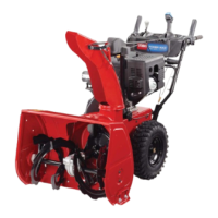
Carefully insert the right side of the upper tubing
over
the end of the lower right side tubing (Fig. 2).
3.
Carefully insert the left side of the upper tubing
into
the end of the lower left side tubing (Fig. 2).
4.
Squeeze the upper tubes together
, and wiggle the upper
tubes down until the mounting holes in the upper and
lower tubing line up (Fig. 2).
1531
1
2
SQUEEZE
Figure
2
1. Upper
tubing
2.
Lower tubing
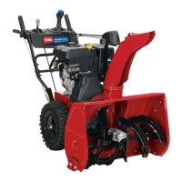
5. Place
the mounting plate over the tubes (Fig. 3). Align
the mounting plate holes with the upper and lower
tubing holes.
1532
2
3
1
4
Figure
3
1. Mounting
plate
2. Shroud
3.
Chute crank
4. Gear
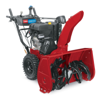
6. Insert
the end of the chute crank through the hole in
the shroud. Turn the chute crank rod
lightly
until the
flattened end drops into the slot in the gear
. Firmly
push the chute crank into the gear until it snaps into
place (Figs. 3 and 4).
1533
1
2
Figure
4
1. Chute
crank
2.
Chute crank gear
7. Secure
the upper and lower tubing and the mounting
plate together with two #10–24 machine screws and
locknuts.
Note:
Position the screw heads on the outside of the
mounting plate.
Be car
eful not to damage the internal
electrical wiring when inserting the scr
ews.
If the
wiring blocks the hole, use a blunt 1/8-in. punch to
carefully route the electrical wiring away from the aligned
holes.
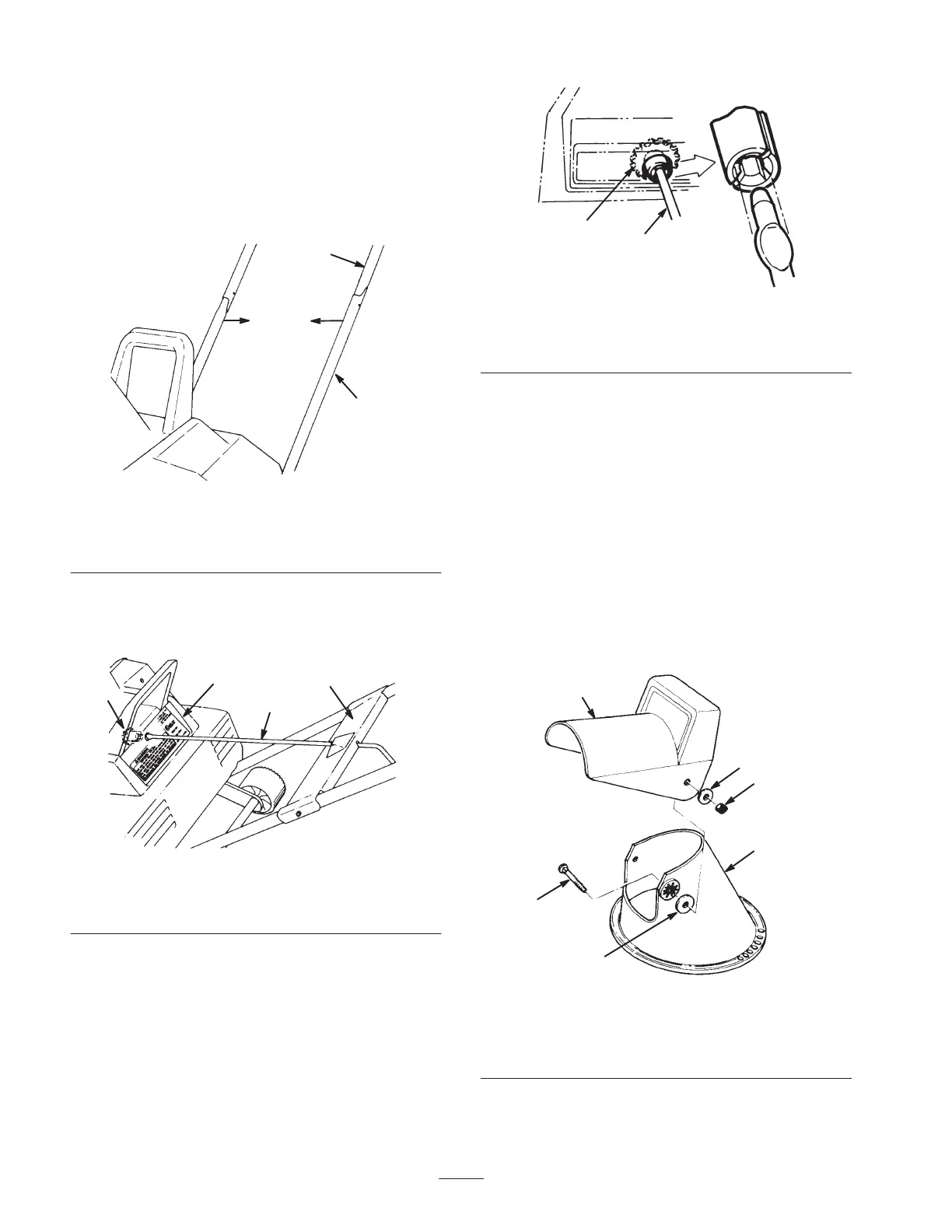
Installing
the Discharge Chute
1. Position
the deflector onto the dischar
ge chute and
align the mounting holes (Fig. 5).
1534
4
3
1
5
6
2
Figure
5
1. Chute
deflector
2. Chute
3.
Rubber washer
4.
Carriage bolt
5.
Metal washer
6. Locknut

 Loading...