15
1
m–1872
Figure 7
1. Valve stem
Operation
Note: Determine the left and right side of the machine from the normal operating position.
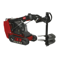
Traction Unit Overview
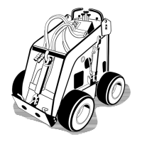
Figure 8 contains a front and back view of the traction unit. Familiarize yourself with all of the traction unit components
listed in Figure 8.
m–5097/5093
5
1
3
2
6
7
8
9
10
11
11
3
4
Figure 8
1. Mount plate
2. Tilt cylinder
3. Loader arms
4. Lift cylinder
5. Fuel tank
6. Wheel
7. Operator platform
8. Engine
9. Auxiliary hydraulic couplers
10. Control panel
11. Lift points
You could fall off of the platform and be seriously
injured during operation.
Do not move the control levers unless you are
standing with both feet on the platform and your
hands are holding the handles.
Caution