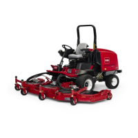
Figure 22
1. Skid
Adjusting the Cutting Unit Rollers
T he cutting unit rollers should be mounted in
the lo w er position when operating in height of
cuts g reater than 2-1/2 inc hes (64 mm) and in the
higher position when operating in height of cuts
lo w er than 2-1/2 inc hes (64 mm).
1. R emo v e the bolt and n ut securing the g ag e
wheel to the cutting unit brac k ets ( Figure 23 ).
Figure 23
1. Gage wheel
2. Align the roller and spacer with the top holes
in the brac k ets and secure them with the bolt
and n ut.
Adjusting the Blade
T o ensure proper operation of the cutting unit,
there m ust be 0.38-0.62 inc h (10-16 mm) clearance
betw een the tips of the wing and center cutting
unit blades ( Figure 24 ).
1. Raise cutting unit so blades are visible and
bloc k center dec k section so it cannot fall
accidentally . Wing dec ks m ust be horizontal
to center cutting unit.
2. R otate a center and adjoining wing blade
so there blade tips are aligned. Measure
distance betw een blade tips , distance should
be appro ximately 0.38-0.62 inc h (10-16 mm)
( Figure 24 ).
Figure 24
3. T o adjust distance , locate adjuster bolt on rear
pi v ot link of cutting unit ( Figure 25 ). Loosen
jam n ut on adjuster bolt. Loosen or tighten
adjuster bolts until 0.38-0.62 inc h (10-16 mm)
clearance is attained, then tighten jam n ut.
4. R e peat procedure on opposite side of cutting
dec k.
Figure 25
1. Adjuster bolt
2. Jam nut
Correcting Mismatch Between Cutting
Units
Due to differences in g rass conditions and the
counterbalance setting of the traction unit, it is
advised that g rass be cut and appearance c hec k ed
before for mal cutting is star ted.
1. Set all cutting units to the desired height of cut;
refer to Adjusting the Height of Cut table in
Specifications , pag e 18 .
2. Chec k and adjust front and rear tractor tire
pressure to 25-30 psi (172-207 kP a).
26

 Loading...


