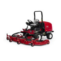
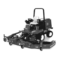
Figure 81
1. Height-of-cut chain
4. Star t the engine and slo wly raise the center
cutting unit.
5. Slo wly raise eac h wing cutting until the center
of g ra vity shifts and the dec k star ts to rotate
into the upright position. Stop the engine and
remo v e the ignition k ey .
Pivoting the Front Cutting
Unit Down
1. Slo wly lo w er wing cutting units until the center
of g ra vity shifts and the center cutting unit
rotates do wnw ard.
2. Sit on the seat, star t the engine , and lo w er the
center cutting unit until it is slightly off of the
floor .
3. Secure the height-of-cut c hains to the rear of
the cutting unit.
4. Pi v ot dampers upw ard into position and secure
with clevis pin and cotter pin.
Adjusting the Cutting Unit
Pitch
Measuring the Cutting Unit Pitch
Cutting unit pitc h is the difference in height-of-cut
from the front of the blade plane to the bac k of
the blade plane . T oro recommends a blade pitc h
of 1/4 inc h (6 mm). T hat is the bac k of the blade
plane is 1/4 inc h (6 mm) higher than the front.
1. P osition the mac hine on a lev el surface on the
shop floor .
2. Set the cutting unit to the desired height-of-cut.
3. R otate 1 blade so that it points straight forw ard.
4. Using a shor t r uler , measure from the floor to
the front tip of the blade . R otate the blade tip
to the rear and measure from the floor to the
tip of the blade .
5. Subtract the front dimension from the rear
dimension to calculate the blade pitc h.
Adjusting the Front Cutting Unit
1. Loosen the jam n uts on the top or bottom of
the height-of-cut c hain U-bolt ( Figure 82 ).
2. Adjust the other set of n uts to raise or lo w er
the rear of the cutting unit and attain the
cor rect cutting unit pitc h.
3. Tighten the jam n uts .
Figure 82
1. Height-of-cut chain 2. U-bolt
Adjusting the Wing Cutting Units
1. R emo v e the cap screws and n uts securing the
castor ar m to the castor fork ( Figure 83 ).
2. R e position the shims , as required, to raise or
lo w er the castor wheel until the cutting unit
has the cor rect pitc h.
3. Install the cap screws and n uts .
52

 Loading...


