Groundsmaster 4100--D/4110--DPage 5 -- 30Electrical System
Main Power, Glow and Cab Power (Groundsmaster 4110--D) Relays
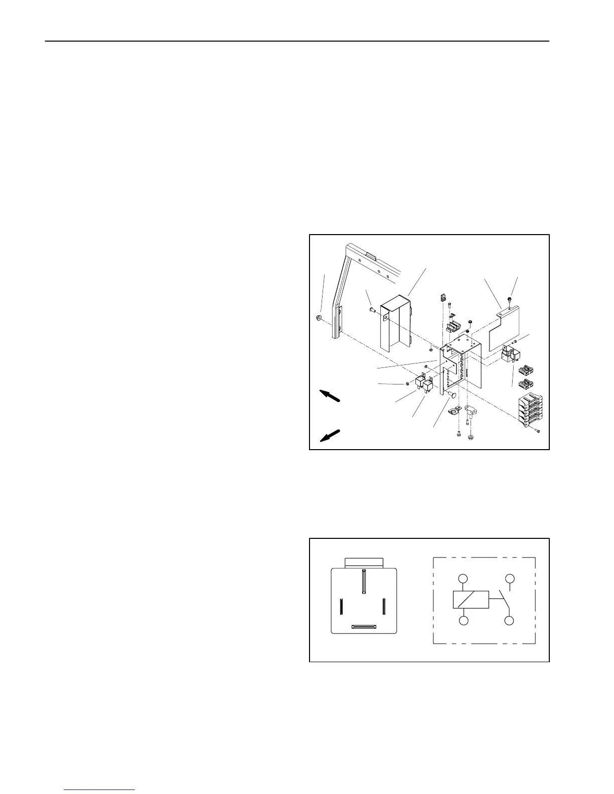
Themainpower,glowandcabpowerrelays arelocated
at the power center behind the operator seat (Fig. 34).
The wire harness is attached to these relays with a four
(4) wire connector (Fig. 35).
The main power relay is used to provide current to the
TEC controllers and most of the fuse protected circuits
(operator seat, power point and optional electric equip-
ment). When the ignition switch is in the ON or START
position, the main power relay is energized.
The glow relay is used to provide current to the engine
glow plugs when the relay is energized by the
TEC--5002controller.TheTEC--5002controlsandmon-
itors the operation of the glow relay.
The cab power relay on Groundsmaster 4110-- D ma-
chines is used to provide current to the operator cab
electricalcomponents.Whentheignitionswitchisinthe
ONorSTARTposition,thecabpowerrelayisenergized.
Testing
1. Park machine on a level surface,lowercuttingdeck,
stop engine, engage parking brake and remove key
from the ignition switch. Raise and support hood.
2. Tomakesurethatmachineoperationdoesnotoccur
unexpectedly, disconnect negative (--) cable from bat-
tery and then disconnect positive (+) cable from battery
(seeBattery Service in the Service and Repairs section
of this chapter).
3. Removecover(item1)andheatshield(item11)from
powercenterandlocaterelaytobetested.Ifnecessary,
removetwo(2)flangenuts andcarriagescrewsthatse-
cure power center to tank support.
4. Disconnect wire harness connector from relay. Re-
move relay from mounting bracket for testing.
NOTE: Prior to taking small resistance readings with a
digital multimeter, short the meter test leads together.
The meter will display a small resistance value (usually
0.5 ohms or less). This resistance is due to the internal
resistanceof themeter andtestleads.Subtract thisval-
uefrom from the measuredvalue ofthecomponent you
are testing.
5. Using a multimeter, verify that coil resistance be-
tween terminals 86 and 85 is approximately 72 ohms.
6. Connectmultimeter(ohmssetting)leadstorelayter-
minals 30 and 87. Ground terminal 86 and apply +12
VDC to terminal 85. The relay should make and break
continuity between terminals 30 and 87 as +12 VDC is
applied and removed from terminal 85.
7. Disconnect voltageandtest leadsfromthe relay ter-
minals. Replace relay if necessary.
8. Secure relay to mounting bracket and connect wire
harnessconnectortorelay.Securepowercentertotank
supportifitwasremoved.Installcover(item1) andheat
shield (item 11) to power center.
9. Connect positive (+) cable to battery and then con-
nect negative (--) c able to battery (see Battery Service
in the Service and Repairs section of this chapter).
10.Lower and secure hood.
1. Cover
2. Screw
3. Flange nut (2 used)
4. Carriage screw (2 used)
5. Screw
6. Mount
7. Lock nut
8. Main power relay
9. Glow relay
10. Cab power relay
11. Heat shield
12. Screw (2 used)
Figure 34
2
3
4
5
1
8
7
6
9
10
FRONT
RIGHT
11
12
Figure 35
86 87
85 30
85 86
87
30
 Loading...


