g020451
Figure61
1.Battery
2.Removetherubberbootfromthepositive
terminalandinspectthebattery.
WARNING
Batteryterminalsormetaltoolscould
shortagainstmetalcomponentscausing
sparks.Sparkscancausethebattery
gassestoexplode,resultinginpersonal
injury.
•Whenremovingorinstallingthe
battery,donotallowthebattery
terminalstotouchanymetalpartsof
themachine.
•Donotallowmetaltoolstoshort
betweenthebatteryterminalsand
metalpartsofthemachine.
WARNING
Incorrectbatterycableroutingcould
damagethemachineandcablescausing
sparks.Sparkscancausethebattery
gassestoexplode,resultinginpersonal
injury.
•Alwaysdisconnectthenegative
(black)batterycablebefore
disconnectingthepositive(red)
cable.
•Alwaysconnectthepositive(red)
batterycablebeforeconnectingthe
negative(black)cable.
3.CoatbothbatteryconnectionswithGrafo112X
(skin-over)grease,ToroPartNo.505-47,
petroleumjelly,orlightgreasetoprevent
corrosion.
4.Slidetherubberbootoverthepositiveterminal.
5.Closethebatterycover.
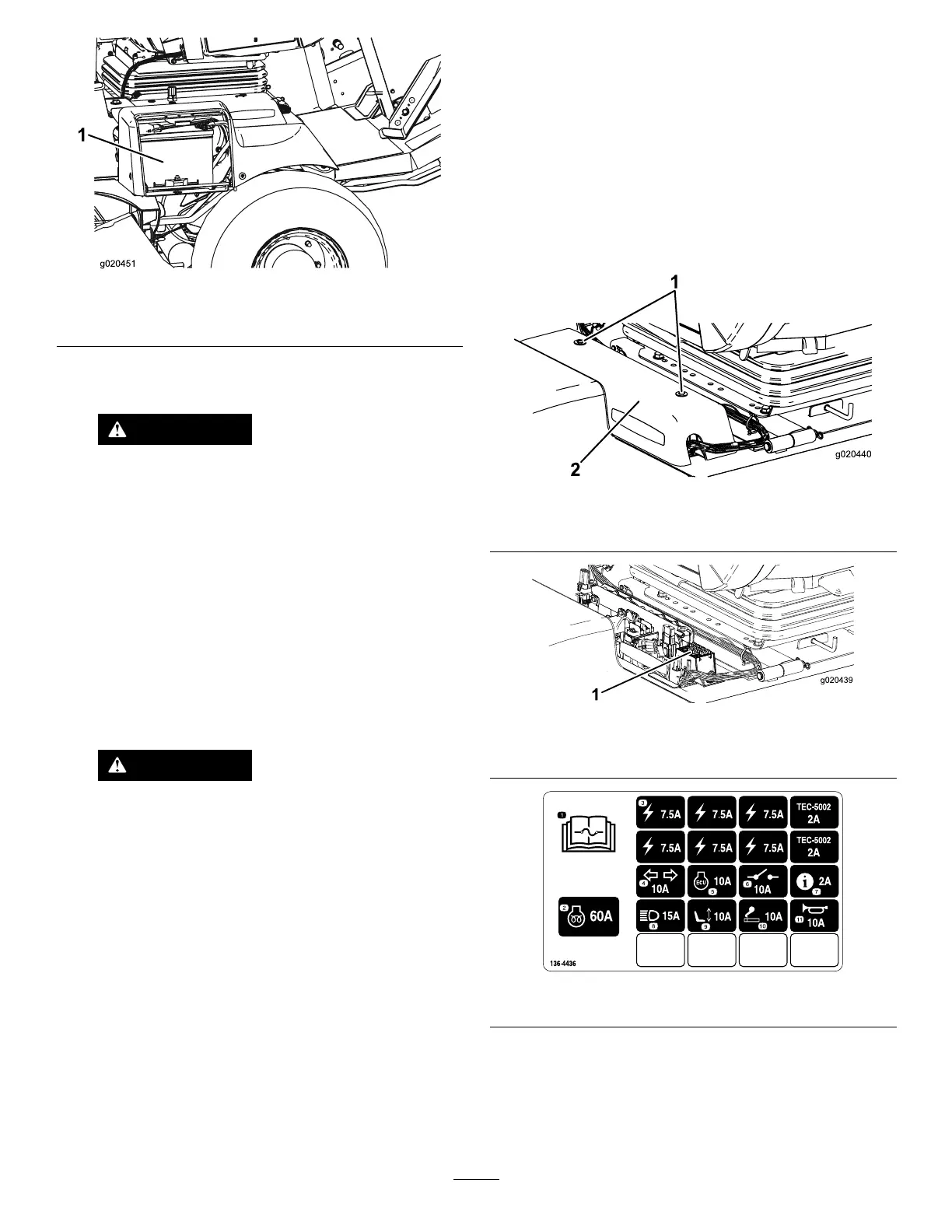
LocatingtheFuses
Thetraction-unitfusesarelocatedunderthe
power-centercover(Figure62,Figure63,andFigure
64).
Removethe2screwssecuringthepower-center
covertotheframeandremovethecover(Figure62).
g020440
Figure62
1.Power-centercover
2.Screws
g020439
Figure63
1.Fuses
g221933
Figure64
Thecabfusesarelocatedinthefuseboxinthecab
headliner(Figure65andFigure66).
Note:Cabmodelonly
55