Figure32
1.Controlrod
5.Neutrallock
2.Clevispin
6.Hairpincotterpin
3.OperatorPresence
Controllever(OPC)
7.Lefthandleshown
4.Handle8.Drivelever
2.Adjustthecontrolrodlengthbythreadingtherodin
oroutoftherodttinguntilthereisa3/16to1/4
inches(5to6mm)clearancebetweenthecontrol
rodandthebottomoftheneutral/parkingbrake
lock(Figure33).
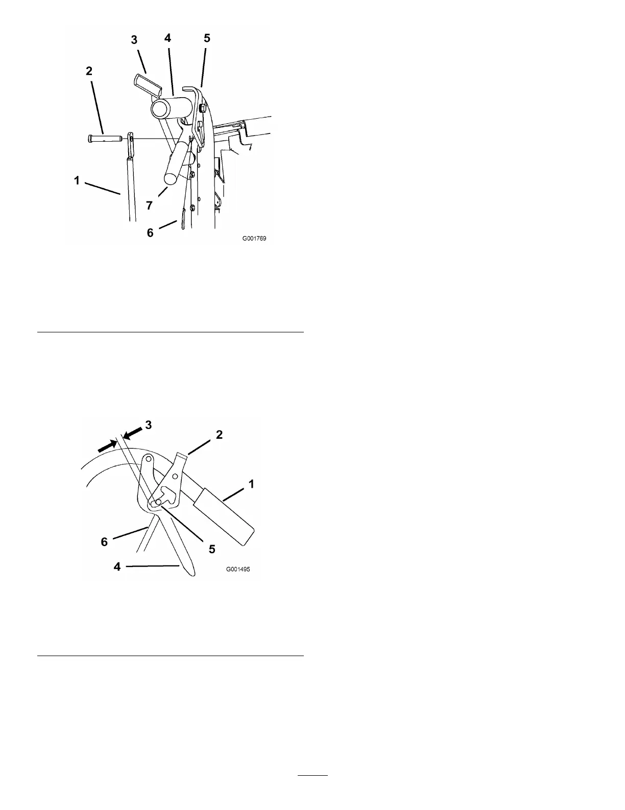
Figure33
1.Handle4.Drivelever
2.Neutral/parkingbrakelock
5.Forwardspeed
3.3/16to1/4inch(5to6
mm)clearance
6.Controlrod
3.Installthecontrolrodtothedriveleverandthe
neutral/parkingbrakelock.Securethecontrolrod
withaclevispinandahairpincotter(Figure33).
4.Checktheoperationofthecontrolrod.Ifyouneed
toadjustit,removethehairpincotterandtheclevis
pinthatsecurethecontrolrodtothedrivelevers.
5.Adjustthecontrolrodlengthbyrepeatingthe
previoussteps.
33