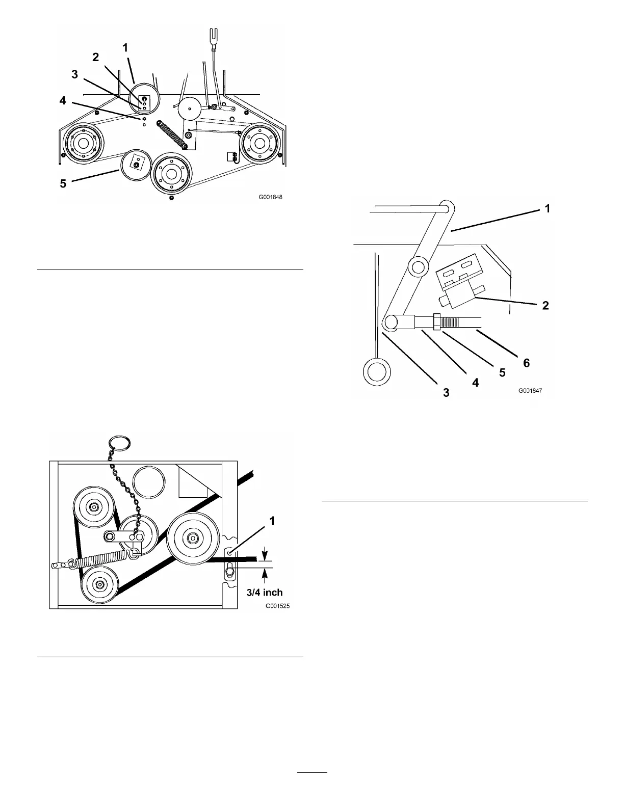
Figure40
1.Rearidlerpulley4.Beltguideinbackposition
2.Middlehole5.Frontidlerpulley
3.Fronthole
8.Checkthebeltguideundertheengineframefor
properadjustment(Figure41).
Note:Thedistancebetweenthebeltguideand
themowerbeltshouldbe3/4inch(19mm)when
youengagethemowerbelt(Figure41).Adjustthe
mowerbeltasnecessary.Thedisengagedbeltshould
notdragorfalloffthepulleywhentheguidesand
belttensionareproperlyadjusted.
9.Checkthebladebrakeadjustment;refertoAdjusting
theBladeBrake.
Figure41
1.Beltguide
AdjustingthePTOEngagement
Linkage
Important:Thebrakeneedstobeadjustedwhen
thebelttensionorthebrakelinkageisadjusted.
ThePTOengagementlinkageadjustmentislocated
beneaththefrontlefthandcorneroftheenginedeck.
1.Disengagethebladecontrol(PTO)leverandsetthe
parkingbrakes.
2.Stoptheengineandwaitforallmovingpartstostop
beforeleavingtheoperatingposition.
3.Engagethebladecontrollever(PTO).
4.Adjustthelinkagelengthtowherethelowerend
ofthebellcrankjustclearstheaxlesupportgusset
(Figure42).
Figure42
1.Bellcrank4.Yoke
2.Safetyswitchlocated
underenginedeck
5.Nut
3.Bellcrankjustclearsthe
gussetwiththePTO
engageded
6.Assistarmlink
5.Makesuretheassistarmisagainsttherearassistarm
stoponthedeck(Figure43).
6.Pushthebladecontrollever(PTO)downtothe
disengagedposition.
7.Theassistarmshouldcontactthefrontassistarm
stoponthedeck.Ifitdoesnotcontact,adjustthe
bellcranksoitisclosertothegusset(Figure43).
38