8
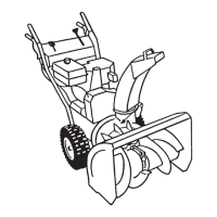
Assembly
Note: Determine the left and right sides of the machine from the normal operating position.
Loose Parts
DESCRIPTION QTY. USE
Handle assembly 1
Bolts 4
Installing the handle assembly
Curved washers 4
Speed selector rod 1
Cotter pin 1
Installing the speed selector rod
Flat washer 1
Spring 1
Installing the traction rod
Flange locknut 1
Installing the traction rod
Lower link 1
Flange nut 1 Installing the auger/impeller drive control
linkage
Flange locknut 1
Discharge chute 1 Installing the discharge chute
Chute control rod assembly (Rod and bracket,
worm gear, and bracket)
1
Bolt, pyramidal washer, and locknut 1 Installing the chute control rod
Bolt 1
Locknut 1
Power cord 1 Starting the engine
Ignition key 1 Starting and stopping the engine