9
Installing the Handle Assembly
1. Remove the tie straps that secure the control rods to the
handle assembly.
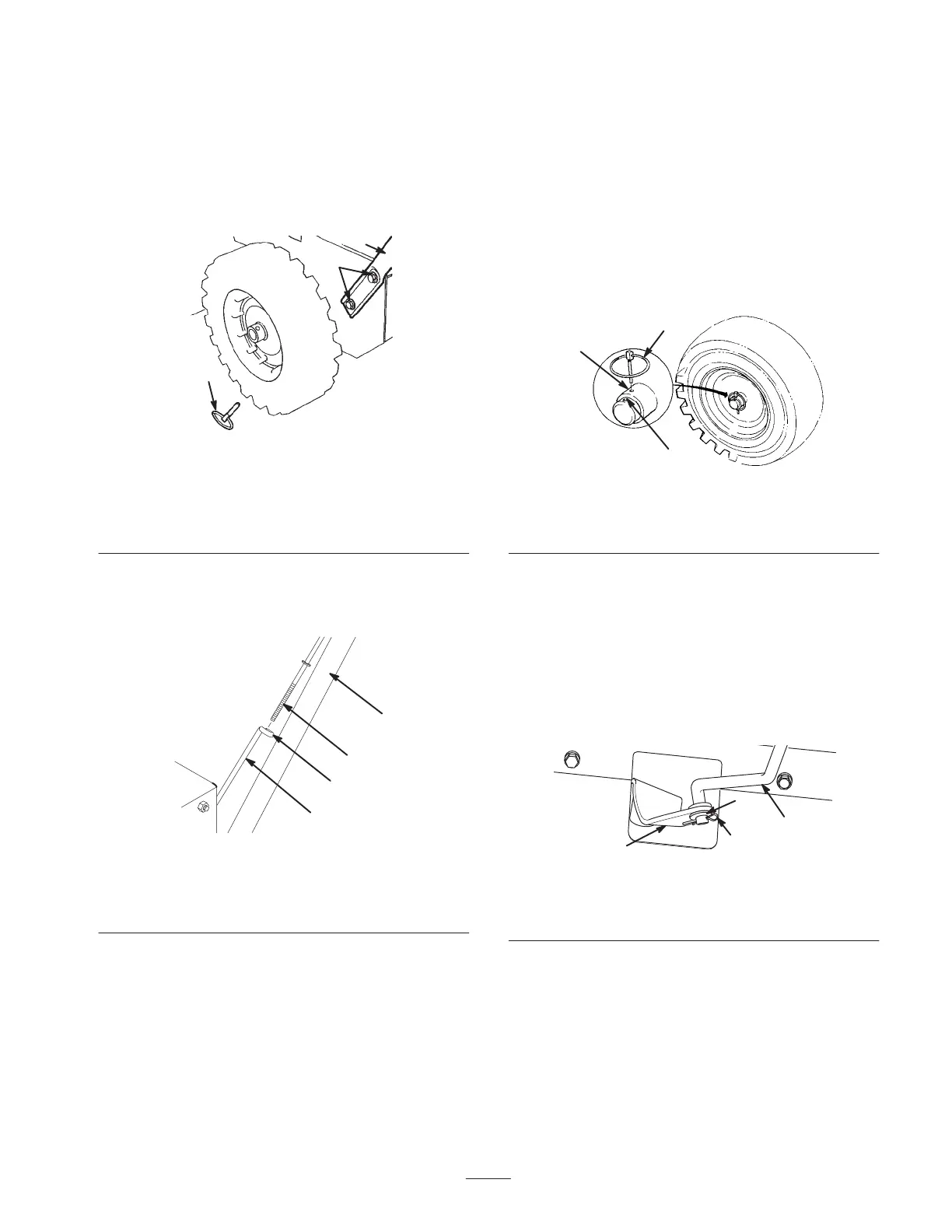
2. Remove the axle pins from both wheels (Fig. 2) and
slide the wheels outward on the axle approximately one
inch (2.5 centimeters).
1
2
3
653
Figure 2
1. Axle pin (2)
2. Bolts and curved
washers (4)
3. Handle assembly
3. Hold the handle assembly in the installation position
and insert the upper traction rod through the loop in the
lower traction rod (Fig. 3).
3
m-4039
4
2
1
Figure 3
1. Lower traction rod
2. Loop
3. Upper traction rod
4. Left side of handle
assembly
4. Position the left side of the handle assembly against the
left side of the snowthrower, align the handle mount
holes with the holes in the side plate, and secure the left
side of the handle assembly with 2 bolts and curved
washers until they are finger tight (Fig. 2).
Note: The concave side of the curved washer goes
against the outside of the handle.
5. Position the right side of the handle assembly against
the right side of the snowthrower, align the handle
mount holes with the holes in the side plate, and secure
the right side of the handle assembly with 2 bolts and
curved washers until they are finger tight.
6. Ensure that both sides of the handle assembly are in line
with each other and then tighten the bolts that hold the
handle assembly.
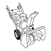
7. Slide the wheels inward and insert each axle pin
through the hole in each wheel hub and through the
inner hole of the axle (Fig. 4).
1
3
2 473
Figure 4
1. Inner axle hole and wheel
hub
2. Outer axle hole
3. Axle pin
Note: To use tire chains (optional), install the axle pins
through the outer axle holes.
Installing the Speed Selector
Rod
1. Pull the speed selector arm (Fig. 5) to the most outward
position.
3
2
1
m-2672
4
Figure 5
1. Speed selector arm
2. Cotter pin
3. Flat washer
4. Speed selector rod
2. Move the speed selector (Fig. 14) on the control panel
to the R
2
(Reverse) position.
3. Rotate the speed selector rod in the trunnion (Fig. 6)
until the bottom end of the rod can slip into the hole in
the speed selector arm (Fig. 5).