ProcedureDescription
Qty.
Use
Bracket1
Bolt(M12-13/4x60mm)
2
Locknut(M12)
2
Hexnut(M10)
1
Bolt(M4)
2
Sensorassembly
1
Nut(M4)
2
Cotterpins
2
Sensorharnessadapter
1
3
Sensor-connectorclip
1
Installtherodcamsensor.
4
Gasket
1
Removingtherotarypumpsupplyand
drainorices.
Monitorcap1
5
Decal1
Installthecapanddecal.
1
InstallingtheRodLoader
Spacer
Partsneededforthisprocedure:
1Thrustwasher
1Washer
1Flangelocknut
Procedure
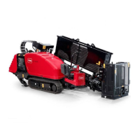
RefertolocationhighlightedinFigure1forthisprocedure.
Figure1
1.Supporttherodloaderassemblytoensurethatthe
pivotpinassemblyisabletomove.
2.Removethesensorassemblyandbracketandsetaside
thehardware(Figure2).
Figure2
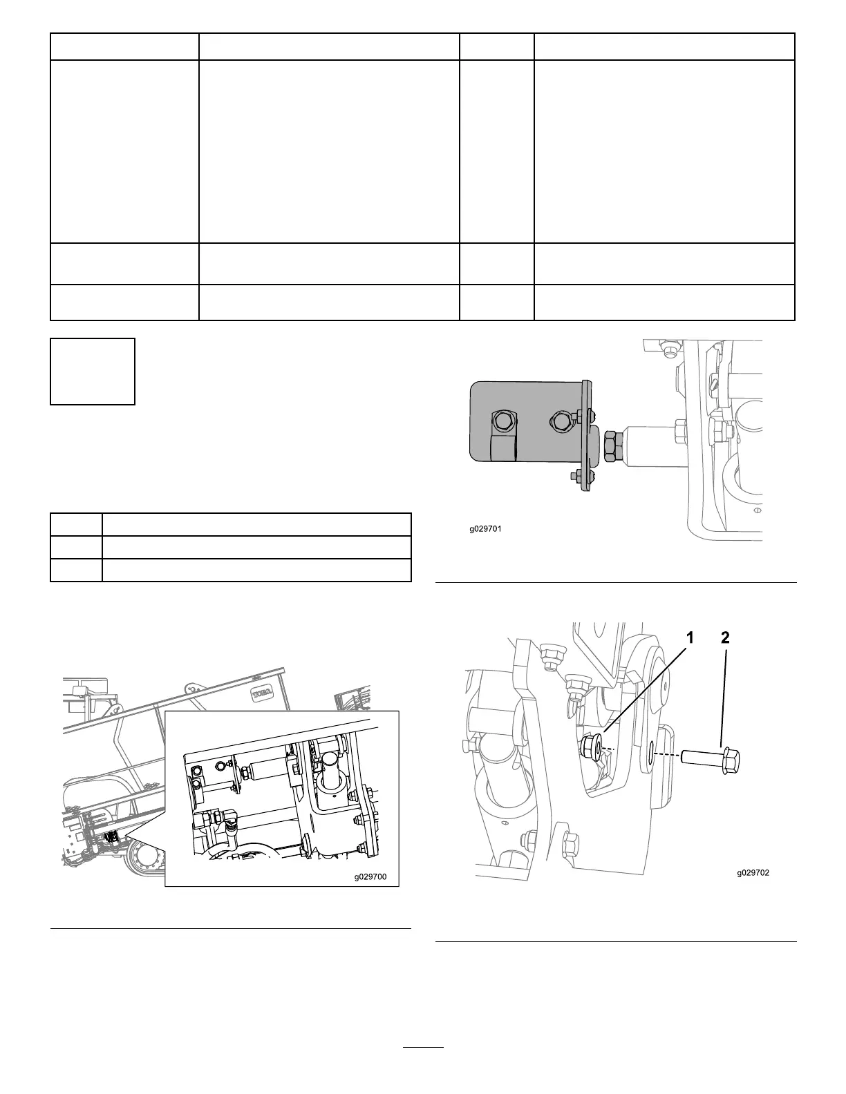
3.RemovetheretainingboltandnutasshowninFigure3.
Figure3
1.Retainingnut(existing)2.Retainingbolt(existing)
4.Movetherod-loaderassemblytothesidetocreatea
gapforthewasher.
2