

V
vbarreraAug 15, 2025
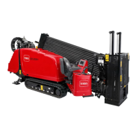
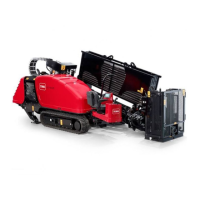
Why does the starter on my Toro Drill not crank?
- GgreentylerAug 15, 2025
If the starter of your Toro Drill doesn't crank, here are a few things to check: * Ensure the battery-disconnect switch is in the On position. * Inspect electrical connections for corrosion or looseness. * Check and replace any blown or loose fuses. * Verify the battery is charged or replace it if necessary. If these steps don't resolve the issue, it may indicate a damaged relay, switch, starter, starter solenoid, or seized internal engine components, in which case you should contact your Authorized Service Dealer.