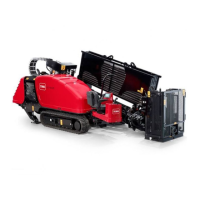
Figure19
1.T40,T30,andT20orices
8.Removethespring(T30)andsupplyorice(T20)from
thecontrol(Figure19).
9.Cleanthesealingsurfacesofthepumphousingand
controlhousing
10.Installthecontrolhousingontothepumpusingthe
newgasket.
Important:Thecontrollinkagepinonthecontrol
mustbeinsertedintotheswash-platelinkinthe
pump.
Note:Usepetroleumjellytohelpholdtheswash-plate
linkinplacewhilethecontrolisinstalled.
Note:Therewillberesistancewhenthefrontedge
ofthecontrolistiltedawayfromthepumphousingif
thecontrollinkagepinisinsertedintotheswash-plate
linkcorrectly.
Note:Ifthecontrollinkagepinisnotproperly
insertedintotheswash-platelink,thepumpwillnot
returntoneutralandtherotarymotorwillspinupon
enginestartup.
11.Installthe6retainingbolts;torquetheboltsto16N-m
(12lb-ft).
12.Connectthecasedrainlineandchecktheyhydraulic
uidlevel;refertotheOperator’sManualforthemachine.
13.Connectthewiringharnesstotherotarypumpcontrol.
14.Wipeupanyspilledoil.
15.Startthemachinetotesttherotarypump.
Note:Iftherotaryoutputspinswhenthemachine
isstartedbuttherotationcommandisnotgiven,the
controllinkagepinisnotproperlyinsertedintothe
swash-platelink.Removeandcapthecasedrainline
andrepeattheabovesteps.
CheckingtheNeutralAdjustment
1.Installa1000psigaugeineachofthedisplacement
controlports(M4andM5).
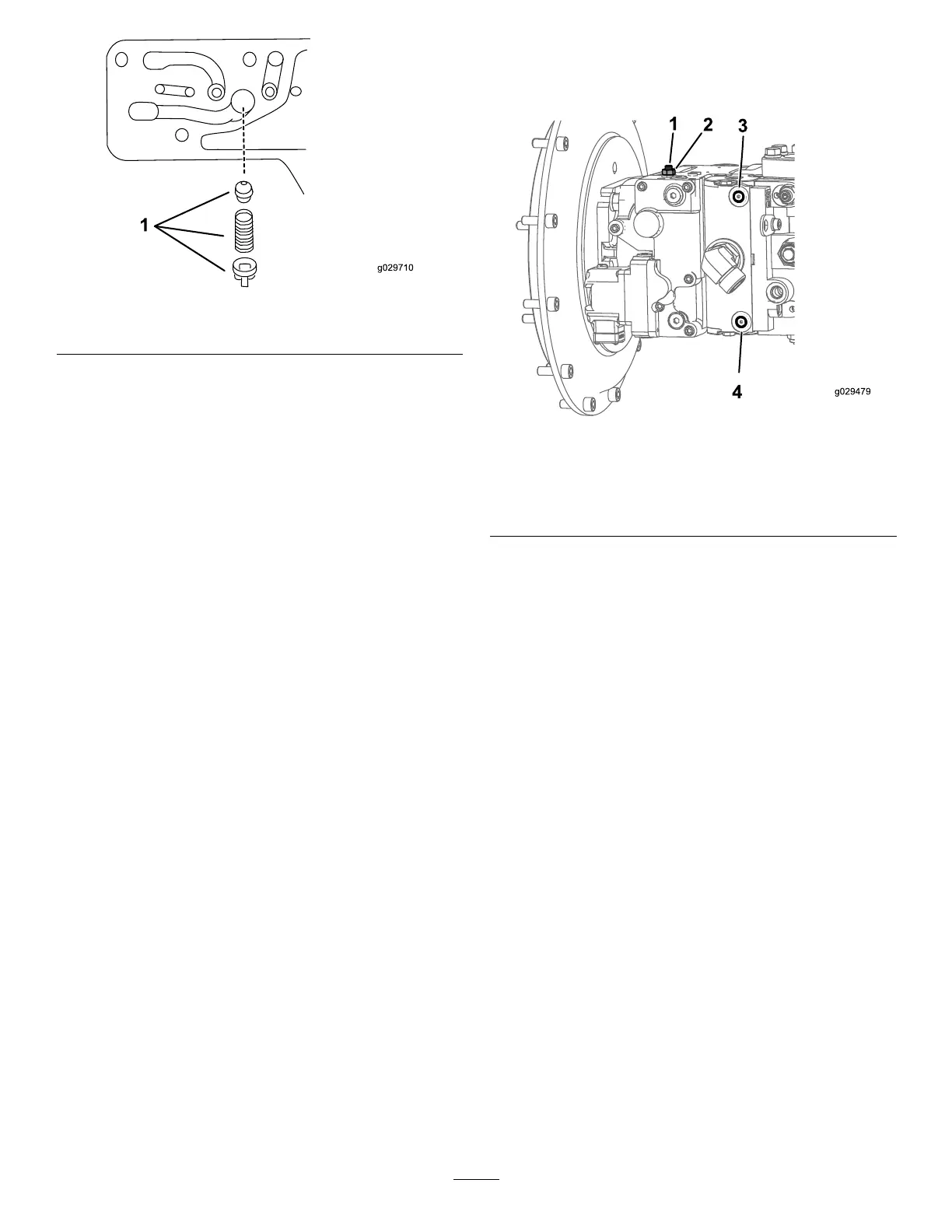
Figure20
1.M72port(adjustingscrew)3.M5port(displacement
controlport)
2.M90port(locknut)4.M4port(displacement
controlport)
2.Disconnecttheelectricalconnectorfromtherotary
pumpcontrol,startthemachine,andbringittohigh
idle.
3.Loosenthelocknut(M90)witha10mmand13mm
hexwrench.
4.Usinga3mmor4mminternalhexwrench,rotate
theadjustingscrew(M72)clockwiseuntilthepressure
increasesin1ofthepressuregauges.
Note:Notetheangularpositionofthewrench.
5.Rotatetheneutral-adjustingscrewcounterclockwise
untilthepressureincreasesbyanequalamountasthe
othergauge.
Note:Notethepositionofthewrench.
6.Rotatetheadjustingscrew(M72)clockwisehalfthe
distancebetweenthelocationnotedinstep(4or5).
Note:Thegaugesshouldreadthesamepressure(case
pressure),indicatingthatthecontrolisinitsNEUTRAL
position.
7.Holdtheneutral-adjustingscrewstationaryandtighten
theneutral-adjustinglocknutto7N-m(62lb-in)forthe
6mmscrewor13N-m(120lb-in)forthe8mmscrew .
8.OncetheNEUTRALpositionisset,stoptheengine,
removethegauges,andremovethegaugeports.
9.Connecttheelectricalconnectortotherotarypump
control.
8
 Loading...