Important:Movetherodloaderassemblyasfar
aspossiblesothatthereisnotagapbetweenthe
rod-loaderpivotandtheloaderassembly(Figure
4).
5.Slidethepivotpinouttoallowtheinstallationforthe
washer(Figure4).
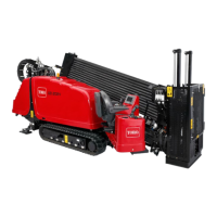
Figure4
1.Washer3.Pivotpin
2.Ensurethereisnogap
here.
6.Installthethickwasher.
Note:Ifthegapisnotlargeenoughforthethick
washer,installthethinwasher.
7.Installthepivotpin.
8.Installtheretainingboltpreviouslyremovedandthe
locknutincludedinthiskitasshowninFigure5.
Figure5
1.Flangelocknut(new)2.Retainingbolt(existing)
9.Torquetheboltto23to29N-m(17to21ft-lb).
2
InstallingtheRodLoader
Sensor
Partsneededforthisprocedure:
1Rod-loadersensor
1Bracket
1Plate
2Flangenut
2
Bolt(M6–1x16mm)
1
Hexnut(M10)
2Flatwasher
1
Bolt(M10–1x40mm)
2
Bolt(M4x10mm)
2
Nut(M4)
1
Sensorharnessadapter
Procedure
1.Applythread-lockingcompoundtotheboltsremoved
inStep2in1InstallingtheRodLoaderSpacer(page
2)andlooselyinstallthebracketusingtheboltsand
R-clampasshowninFigure6.
Figure6
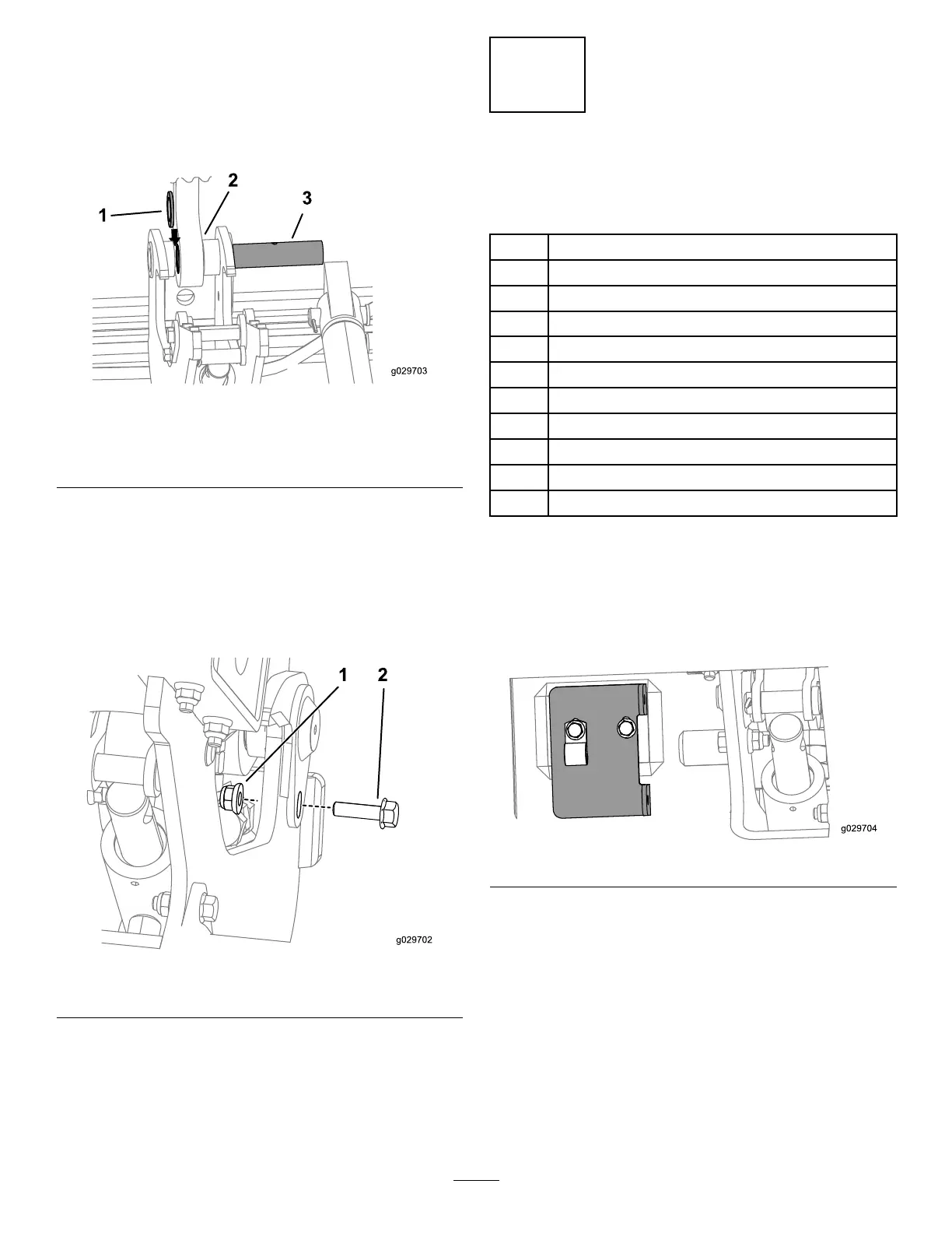
2.Looselyinstalltheplateonthebracketusing2bolts
(M6–1x16mm)and2angenutsasshowninBox
AofFigure7.
3

 Loading...