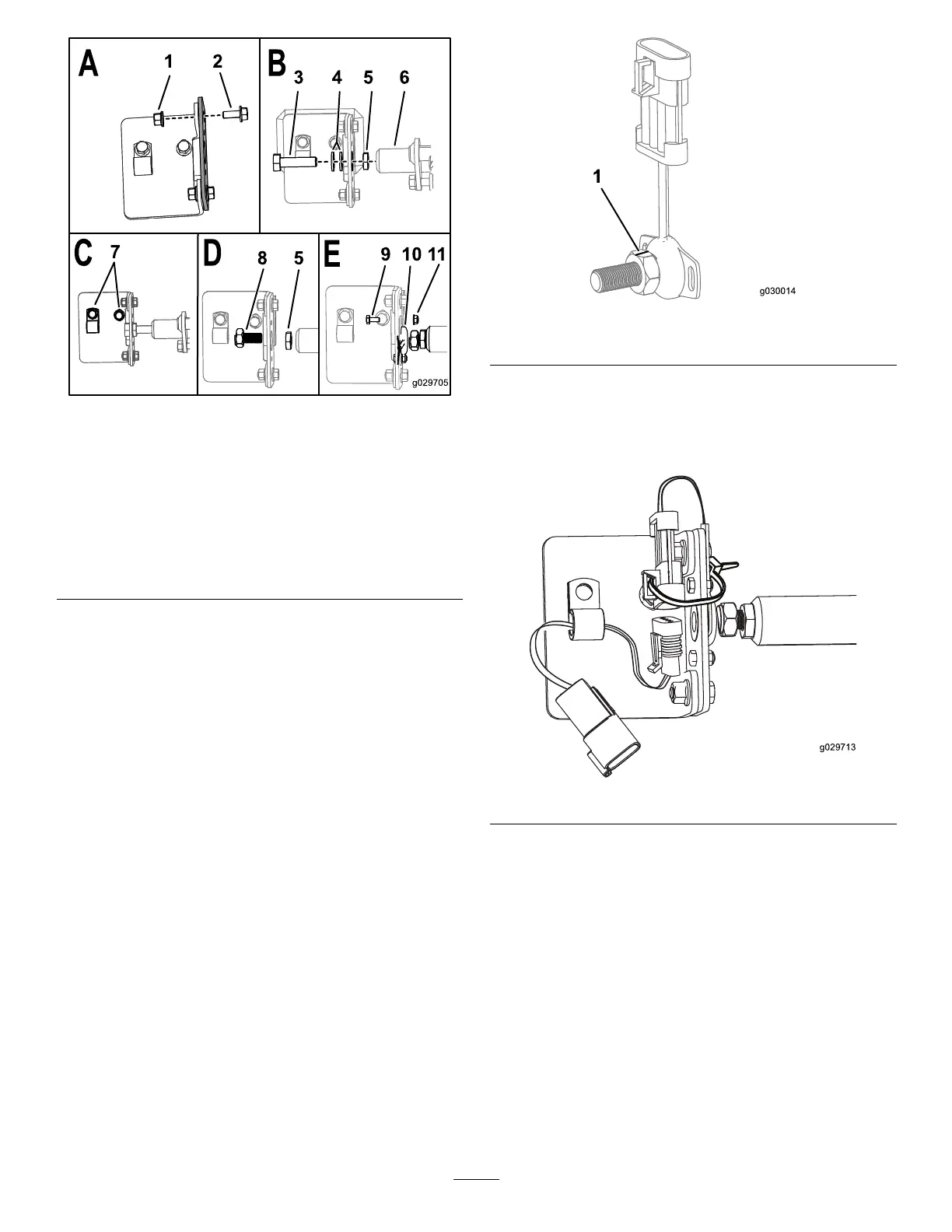
Figure7
1.Flangenut7.Applythread-locking
compoundwhen
tighteningthesebolts.
2.Bolts(M6–1x16mm)8.Sensor-magnetbolt
3.Bolt(M10–10x40mm)9.Bolt(M4x10mm)
4.Flatwashers
10.Sensor
5.Hexnut
11.Nut(M4)
6.Pivotpin
3.Installthebolt(M10-1x40mm),2atwashers,and
thehexnut(M10)ontothebracketplateandpivotpin
asshownBoxBofFigure7.
Note:Usethewasherstocenterthebracketandplate.
4.Tightenallofthehardwarethatissecuringthebrackets
tothemachine(BoxCofFigure7).
5.Torquetheboltsto972to1198N-cm(86to106in-lb).
6.Torquethebolts(M6)to972to1198N-cm(86to106
in-lb).
7.Removethebolt(M10–1x40mm),2atwashers,and
thehexnutfromthebracketplateandpivotpin(Box
BofFigure7).
8.Installthesensormagnetboltandhexnutintothe
pivotassemblyasshowninBoxDofFigure7.
9.Installthesensorontothebracketusing2bolts(M4
x10mm)and2nuts(M4–0.7inch)asshowninBox
EofFigure7.
Note:Usethread-lockingcompoundontheboltsif
thelocknutsarenotnylonlocknuts.
10.PlacethecamassemblyintheHOMEpositionand
ensurethatthenotchinthemagneticsensorboltis
linedupwiththewiresonthesensorasshownin
Figure8.
Figure8
1.Notch
11.Ensurethatthegapbetweenthemagneticsensorbolt
andthesensoris0.12to0.24inch.
12.Securethesensortothebracketwithacabletieas
showninFigure9.
Figure9
13.Torquethebolts(M4)to2.2to2.7N-m(19to23ft-lb).
14.Attachthesensor-harnessadaptertotheR-clampon
thebracketandattachtheadaptertothesensoras
showninFigure9.
15.Usethesensorharnessadaptertoconnectthesensor
tothewiringharnessofthemachine.
4

 Loading...