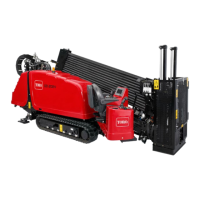
Figure16
1.Sensor2.Sensor-harnessadapter
16.Attachthesensor-harnessadaptertothesensoras
showninFigure16.
17.Connectthesensor-harnessadaptertothewiring
harnessonthemachine.
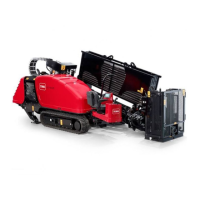
18.SecurethewiringharnesstotheR-clampwithacable
tieasshowninFigure17.
Figure17
1.Wiringharness(existing)
19.Torquetheboltsto2.2to2.7N-m(19to23in-lb).
20.Installtheelevatorcylinderwiththe2cotterpins
includedinthiskitasshowninBoxCofFigure13.
21.Usethesensorharnessadaptertoconnectthesensor
tothemachineswiringharness.
4
RemovingtheRotaryPump
SupplyandDrainOrices
Partsneededforthisprocedure:
1
Gasket
Procedure
Important:Allowtheenginetocool.
1.Placeadrainpanundertheyrotarypump
2.Capoffthecasedrainlinefromtherotarypumpto
minimizehydraulicuidloss.
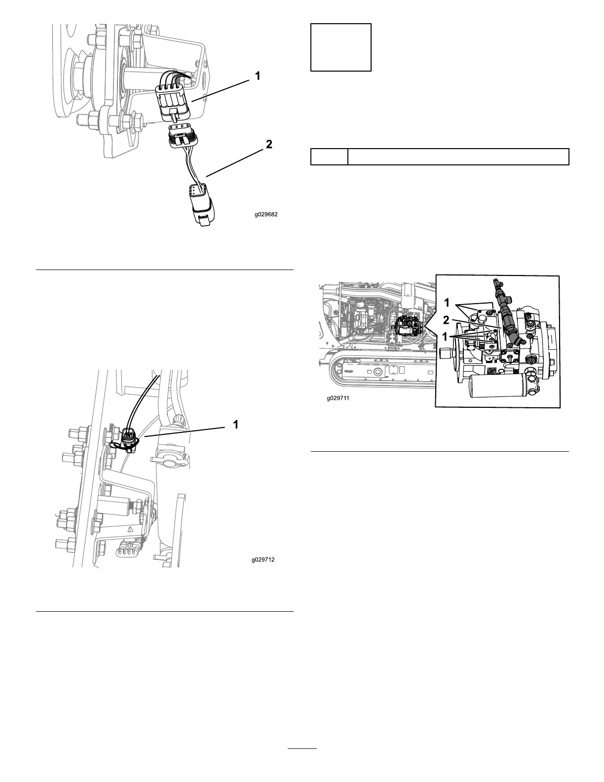
Figure18
1.Boltstoberemoved
2.Capoffthecasedrainline
3.Cleantheexternalsurfaceoftherotarypump.
4.Unplugthewiringharnessfromthepumpcontrol.
5.Removethe6boltsasshowninFigure18.
6.Removethecontrolfromthepumphousing.
Note:Oilwilldrainfromthecasewhenthehousing
isremoved.
7.Useneedlenoseplierstopulltheretainingclip(T40)
fromthecontrol(Figure19).
7
 Loading...