5.Installthebolt(M10-1x40mm),2atwashers,and
thehexnut(M10)ontothebracketplateandpivotpin
asshownBoxCofFigure12.
Note:Usethewasherstocenterthebracketandplate.
6.TightenthehardwareasshowninBoxDofFigure12.
7.Torquethebolts(M12)to80to100N-m(59to73
ft-lb).
8.Removethebolt(M10-1x40mm),2atwashers,and
thehexnutfromthebracketplateandpivotpin(Box
CofFigure12).
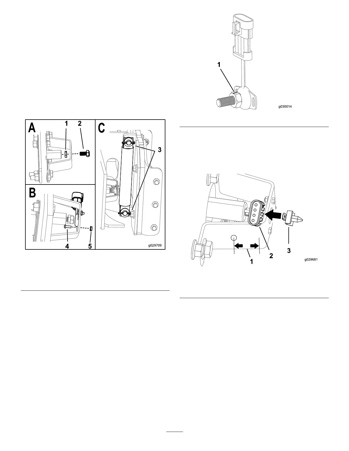
9.Installthesensor-magnetboltandhexnutintothe
pivotassemblyasshowninBoxAofFigure13.
Figure13
1.Hexnut
4.Bolts(M4x10mm)
2.Sensor-magnetbolt5.Nuts(M4)
3.Cotterpins
10.Installthesensorontothebracketusing2bolts(M4x
10mm)and2nuts(M4)asshowninBoxBofFigure
13.
Note:Usethread-lockingcompoundontheboltsif
thelocknutsarenotnylonlocknuts.
11.PlacethecamassemblyintheHOMEpositionand
ensurethatthenotchinthemagneticsensorboltis
linedupwiththewiresonthesensorasshownin
Figure14.
Figure14
12.Ensurethatthegapbetweenthemagneticsensorbolt
andthesensoris0.12to0.24inches.
13.Ifyourbracketdoesnothaveahole,measurein11/14
inchfromtheedgeofthebracketasshowninFigure
15anddrilla1/4inchhole.
Figure15
1.11/4inch3.Sensor-connectorclip
2.Sensor
14.Attachthesensor-connectorcliptothesensoras
showninFigure15.
15.Plugthesensor-connectorclipintotheholeasshown
inFigure16.
6

 Loading...