36
Hydraulic fluid escaping under pressure can
penetrate skin and cause injury.
• If hydraulic fluid is injected into the skin it must
be surgically removed within a few hours by a
doctor familiar with this type of injury;
otherwise, gangrene may result.
• Keep your body and hands away from pin hole
leaks or nozzles that eject high pressure
hydraulic fluid.
• Use cardboard or paper to find hydraulic leaks.
• Safely relieve all pressure in the hydraulic
system before performing any work on the
hydraulic system.
• Ensure that all hydraulic fluid hoses and lines
are in good condition and all hydraulic
connections and fittings are tight before
applying pressure to hydraulic system.
Warning
Checking the Hydraulic Lines
After every 100 operating hours, check the hydraulic lines
and hoses for leaks, loose fittings, kinked lines, loose
mounting supports, wear, weather, and chemical
deterioration. Make necessary repairs before operating.
Note: Keep areas around the hydraulic system clean from
grass and debris buildup.
Waste Disposal
Engine oil, hydraulic oil, and engine coolant are pollutants
to the environment. Dispose of these according to your
state and local regulations.
Adjusting the Handle Neutral
Position
If the motion control levers do not align or move easily into
the console notch, adjustment them. Adjust each lever,
spring, and rod separately.
Note: The motion control levers must be installed correctly.
See Installing the Motion Control Levers in the Setup
instructions.
1. Disengage the PTO, move the motion control levers to
the neutral locked position, and set the parking brake.
2. Stop the engine, remove the key, and wait for all
moving parts to stop before leaving the operating
position.
3. Tilt the seat forward.
4. Begin with either the left or right motion control lever.
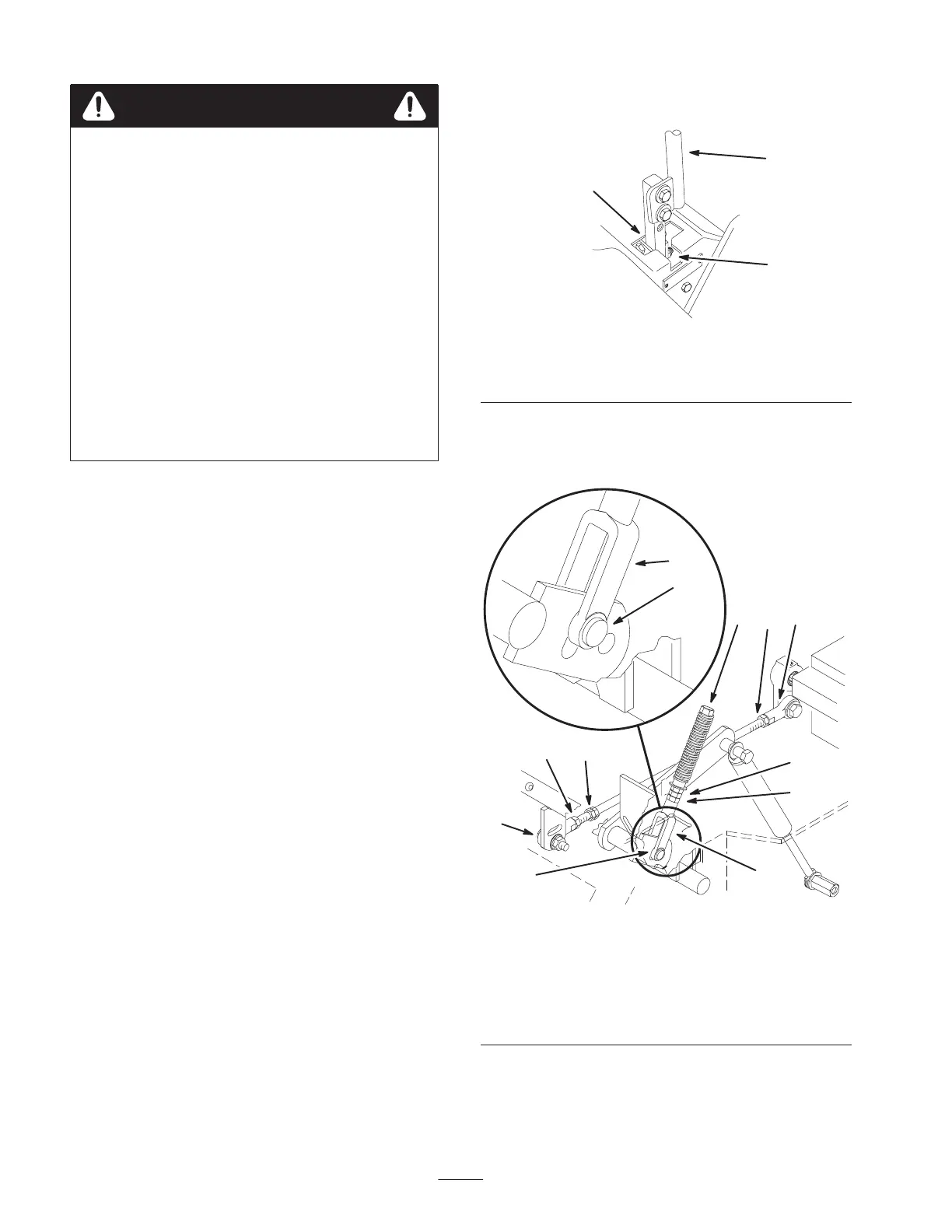
5. Move lever to the neutral position but not locked
(Fig. 43).
2
m–6282
1
3
Figure 43
1. Neutral locked position
2. Control lever
3. Neutral potion
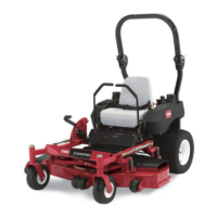
6. Pull the lever back until the clevis pin (on the arm
below the pivot shaft) contacts the end of the slot (just
beginning to put pressure on the spring) (Fig. 44).
m–4118
1
1
2
6
4 3
2
7
9
9
8
8
Figure 44
1. Clevis pin in slot
2. Nut
3. Nut—Left hand thread
4. Adjustment bolt
5. Pump rod
6. Double nuts
7. Jam nut
8. Yoke
9. Ball joint
7. Check where the control lever is relative to the notch in
the console (Fig. 43). It should be centered, allowing
the lever to pivot outward to the neutral lock position.